Choosing a Proper Relay AmperageHow to calculate for the Correct Relay |
Relay Ratings and Limits
Relays are normally specified with separate AC and DC contact ratings. These ratings indicate the maximum voltage and current that the relay contacts are designed to switch under specific test conditions.It is important to understand that a relay’s current rating depends on the switching voltage and the type of load. For example, a relay rated for 5 Amps at 125 VAC may only be rated for 2.5 Amps at 250 VAC. Likewise, a relay rated for 5 Amps at 24 VDC may be limited to lower current at higher DC voltages, or may allow higher current at lower DC voltages.
Always refer to the relay’s published contact rating table when available. Look for the Data Sheets tab on any product page for the installed relay data sheet.
Volts × Amps = Watts - A Practical Safety Check
A simple way to perform a quick sanity check is to multiply the rated voltage by the rated current. This gives an approximate maximum switching power in watts.Relays normally have separate AC and DC contact ratings. Calculate both values and make sure your load does not exceed the appropriate rating.
| AC Volts × AC Amps = AC Watts | DC Volts × DC Amps = DC Watts |
|
Example: A 5-Amp relay rated at 240 VAC 5 × 240 = 1,200 AC Watts |
Example: A 5-Amp relay rated at 24 VDC 5 × 24 = 120 DC Watts |
| When switching AC loads, make sure the load power does not exceed 1,200 watts when using a 5-Amp relay rated at 240 VAC. | When switching DC loads, make sure the load power does not exceed 120 watts when using a 5-Amp relay rated at 24 VDC. |
Resistive and Inductive Loads
Relay contact ratings are usually specified for resistive loads. Resistive loads are electrically quiet and draw relatively stable current, such as heaters and LED lighting.Inductive loads create large electrical transients when switched. Typical inductive loads include motors, solenoids, contactors, and transformers. These loads place significantly more stress on relay contacts and greatly reduce contact life if not properly protected.
Startup and Running Loads
Inductive loads typically draw significantly higher current when power is first applied. This inrush current is often 2 to 3 times higher than the normal running current.For example, a motor rated at 5-Amps at 125 VAC may draw 10 to 15 amps during startup. Once the motor reaches operating speed, the current usually drops back to the rated value.
When switching inductive loads, always select a relay whose contact rating safely exceeds the expected startup (inrush) current. In this example, a 20–30 Amp relay would be recommended for maximum reliability and long contact life.
Induction Suppression
 One
of the most important - and most often overlooked - aspects of relay control is inductive load
suppression.
One
of the most important - and most often overlooked - aspects of relay control is inductive load
suppression.
Any device that contains a magnetic coil (motors, solenoids, relays, and transformers) generates a high-voltage transient when power is removed. This voltage spike can:
- Shorten relay contact life
- Create electrical noise that interferes with the controller
- Cause communication errors or unexpected resets
- Require power cycling to restore normal operation
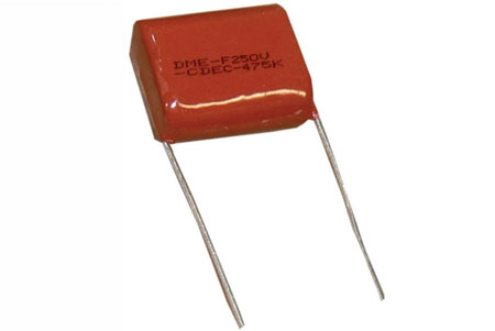
Capacitors are available at checkout.
 |
Relay Pros, LLC 800-960-4287 sales@relaypros.com |
Relay Pros, LLC 780 2nd Street Osceola, MO 64776 |
|
| www.relaypros.com | |||