Wi-Fi N-Button Push Notification SetupInstructions for Wi-Fi Push Notification & N-Button |
Wi-Fi SetupThe Wi-Fi Module must be configured in order to connect to your network and so that it can be accessed through N-Button.1. Install the Wi-Fi Module into the Wi-Fi Module Configuration Board  - Remove the Wi-Fi module from the Push Notification Board and install it in the configuration board (Zigmo) as shown being careful not to bend any pins. 2. Connect USB cable to the configuration board and to your computer - When you connect the USB cable to the Zigmo the USB LED should light up solidly. It may take a couple of seconds for this to occur. Virtual COM Port Drivers may be required before the USB Configuration Board can be used. - Windows 10, 8 and 7 typically recognizes this device without drivers, if needed the latest drivers may be downloaded and installed from the following location for all operating systems: http://www.ftdichip.com/Drivers/VCP.htm. This link also contains installation instructions appropriate to your operating system. 3. Install NCD Base Station Base Station Software for configuring the Wi-Fi Module can be downloaded at: www.relaypros.com/start.htm. 4. Select the appropriate Com Port for you Wi-Fi module - Run Base Station Software - Choose the appropriate Com Port from the ‘Select Connection’ window. - Click ‘WiFi Setup’ Note: If you do not see the WiFi Setup button on the lower right hand corner click the 'More' button in the upper right hand corner. 
5. WiFi Configuration A - Enter Network Name (SSID): Your Wi-Fi Module will already have a network name of the router to which it was connected. This is where you will enter the information for your network. NETWORK SSID MUCH BE ENTERED WITH NO SPACES. If you do not know this information, you can select “Scan for Networks” to the right for the “Enter Network Name” text box. This will show all Wi-Fi networks that are in range of your module. Choose the appropriate network and click “Select”. This process will fill in the Network Name for you. B - Enter the Network Passphrase: This will be the password that allows access to your wireless router. C - Device Name: Makes the device easier to find on your network. This name can be whatever you choose. D - Device Port Number: By default this is set to 2101. This is the number that is most commonly used and is recommended, however, it can be set to any value. E - Join Network on Power Up: It is recommended that you leave this option checked. “Join Network on power up” means that as soon as the module powers up it attaches to the network. This pick chip on the relay board your module will later be installed into has no way to command the Wi-Fi module to connect so checking this option will allow automatic connection. F - Socket Timeout: By default this box is unchecked. When using a mobile device, it is recommended to check this box. G - DHCP or Static IP Address: By default the module is set for DHCP which in most cases is the recommended setting. This means that your module will obtain an IP address from the router. If you are using the Wi-Fi Module on a network switch or you do not have a DHCP Server, choose Static IP Address option instead. You can then enter the IP address and other information into the boxes that appear: - 1) Static IP Address, 2) Default Gateway, 3) Subnet Mask. This device will then always try to use the IP Address ***Make sure that the IP Address is reserved on the network so no other devices may obtain that address*** 
6. When all setting changes are complete, click “Save WiFly” button. This will write all settings into the module. A progress bar will indicate the completion of the configuration. 7. When storing is complete you will see the words “READY” and “Associated!” Further down, you will also see the device’s IP Address. If using DHCP, you might want to write this down. When you place the module into the Relay board from the Configuration board, you will need to know the module’s IP Address. 
8.Close Software 9. Install Module into a Relay Board Disconnect the USB cable from the Zigmo. Remove Wi-Fi module from the Configuration Board and install it back in the Push Notification board. Again, be careful not to bend any pins. The module fits snuggly so there is no need to solder or affix the module to the board in any way. The module may need to be removed for any network changes in the future. 10. Connect Power Supply to the Wi-Fi Module The LED should light on the Wi-Fi Module as soon as power is applied. Eventually the green LED light on the Wi-Fi Module should be flashing slowly. This indicated a good connection to the router. The board is now accessible over your Wi-Fi network and has an IP address. Proceed to the next section and setup N-Button Software. N-Button Communication & Scan Channel Setup1. Download and install the version of N-Button Pro or N-Button Lite that you purchased with the board.N-Button Lite: http://serialporttool.com/download/NButton/NButtonLite.zip N-Button Pro: http://serialporttool.com/download/NButton/NButtonPro.zip 2. Plug in power and make sure the Wi-Fi push notification board is in the SAME network with the computer having N-Button installed. Note: You need configure Wi-Fi module for connection to your wireless network. You will find the details about this configuration in Wi-Fi Quick Start Guide at the bottom of this page. Once the Wi-Fi push notification board is connected, the green LED light on Wi-Fi interface will flash with about one second interval continuously if it’s UDP connection; or the green LED light will not flash but the smaller yellow LED light beside it will flash for TCP connection. 
3. Run N-Button. Click Device Manager –> New to add Wi-Fi push notification board Manufacturer –> National Control Devices Board Type –> Push Notification IP Address/Mac Address –> Double-click the Discovered Network Device item, IP Address and Mac Address will be displayed automatically. TCP/UDP Port –> Keep default setting for TCP Port (2101) and UDP Port (3333). Wi-Fi –> Be sure to check this option. TCP Connection –> Uncheck it to allow the Wi-Fi push notification board works with more than one computer. Check it to allow the board work with ONE computer only. Note: It should be shown on the Discovered Network Devices list automatically if you have Wi-Fi push notification board connected to the same network with your computer. If not, try to set up Windows Firewall to allow N-Button to communicate on your network. 
Click OK for above panels, and back to N-Button Manager panel. 4. Click Scan Channel to open Properties – Scan Channel. Select Device, Bank ID, Channel ID, Style for Scan Channel widget. 
Once you have selected the Device and Style of your widget Click OK to close Scan Channel Window and return to N-Button Manager Window. –> Click OK in N-Button Manager Window to exit. You will now see the Scan Channel widget you created showing on your desktop with Red color. 
5. Using a dry contact (no voltage) close the contacts of the input you have set, you will see the Scan Channel widget on your desktop turn to Green. Release the button, the widget turns to red again. 
The Wi-Fi push notification board is now working with N-Button software. The widget you created is now showing the status of the input. To send text message and/or email follow the steps below. Setting Up Text/Email1. Right click on the widget you just created and select N-Button Manager to open N-Button Pro/Lite Manager again.–> Click Automation to open the Automation Manager Window. –> Click New in the Automation Manager Window to open the Rule Type Window. –> Click Push Notification Contact Closure Rule 
2. Select Settings under Push Notification Contact Closure to select the device you created and the channel you want to use. Select Settings under Action When Status Changes from Open to Close. Under Action Type select Send Email. Enter the Gmail account information you will be using to send the email. Then enter the address where you want the email sent, for more than one recipient separate the addresses with a comma. Add your Subject and message. You can also set a message for other actions such as when the contact closure opens or send messages in intervals until the contact closure opens. –> Click OK in all open windows and return to the desktop. 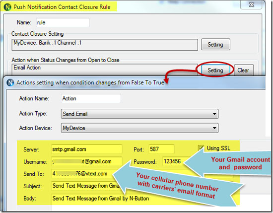
3. After finishing all above settings, all recipients will receive an email once the contact closure input on the board changes state. To test, close the contact input on the push notification board and check your email Note: If you use Gmail, you need turn on for “Allow less secure apps” on your Gmail Account –> Sign-in security panel, shown as below. 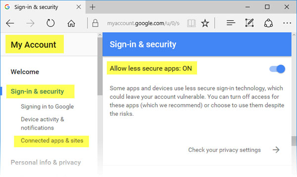
Wi-Fi Push Notification Video |
Data Sheets & Quick Start GuidesBelow are the Data Sheets Quick Start Guides for this software. These are the guides that will help you setup the software and get it configured. The Wi-Fi Push Quick Start Guide is a Step-By-Step guide to getting the Wi-Fi Module on your network and setting up N-Button Software. |

