Reactor Relay 4-Channel 10-Amp with USB Interface
LRR410_USB
Sensor-Controlled Relay Automation
The LRR410_USB continuously monitors up to 8 analog (0 to 5 VDC) or contact closure inputs and automatically controls its onboard relay based on the conditions you configure. Set relays to activate above or below a sensor threshold, remain energized within a specific operating range, or trigger after an adjustable time delay.From turning on a fan when a temperature rises to keeping a light on for 10 minutes after motion is detected, the Reactor Controller automates your equipment without requiring custom programming. Simply configure your logic with the included Base Station Software, upload it to the controller, and let Reactor do the rest.
Configure with USB. Operate Automatically.
The LRR410_USB uses a USB connection for quick and simple configuration with the included Base Station Software. Build automation with an easy point-and-click interface, upload your settings, and disconnect the computer.Once configured, the Reactor Controller continuously monitors connected sensors and contact closures, making decisions and controlling the relay completely on its own. Reconnect the USB cable anytime to update your configuration or manually control the relay when needed.

- OVERVIEW
- Automation
- Applications
- Technical
- Board Features
- Power & More
- Relay Logic
- Induction
- ACCESSORIES
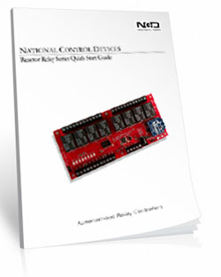
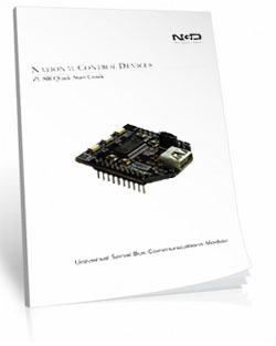
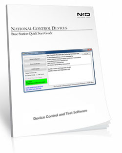
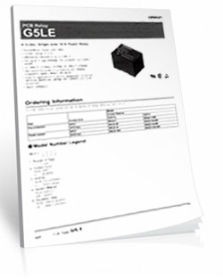
- Data Sheets
Reactor Relay at a Glance
- 4 10-Amp Relay Installed
- Single Pole Double Throw (SPDT) Relay
- Wire to Normally Open or Normally Closed Position
- 14 Guage Solid Core Wire Capacity
- Temperature Rating -40° C to 85° C
- Not-Expandable - Easy to Configure - Point-and-Click Base Station Software Included
- Intelligent Sensor Control
- Controls Relays from Sensors or Contact Closures
- Accepts 0 to 5 VDC Sensor Inputs
- 256 Programmable Trigger Points
- Trigger Above, Below, or Within a Sensor Range
- No Programming Required
- Operates Without a Computer After Configuration
- Free Base Station Software Download
)
Configure Once. Operate Automatically.
Use the included Base Station Software to configure your Reactor Controller, upload the settings, and disconnect the computer. Reactor continues monitoring sensors and controlling relays automatically.
Sensor Activated Relay Controller
"Intelligent Relay Control Starts Here!"
Configure with USB. Operate Automatically
Every Reactor Controller is configured using the included Base Station Software and a imple USB connection. Create your automation using an easy point-and-click interface, upload the configuration to the controller, and disconnect the computer.Once configured, the Reactor continuously monitors connected sensors and contact closure inputs, automatically controlling relays according to the conditions you've defined. Need to make changes? Simply reconnect the USB cable, update your configuration, and upload it to the controller.
Upload your configuration, disconnect the computer, and let Reactor continuously monitor sensors and control relays automatically.
Intelligent Relay Automation
 Reactor Controllers go far beyond turning relays on and off. Configure sensor thresholds that activate relays above, below, or within a specific operating range. Add programmable time delays to keep equipment running after an event or automatically turn outputs off after a preset time.
Whether you're controlling a fan, pump, warning light, or alarm, Reactor continues making decisions long after the computer has been disconnected.
Build Powerful Automation
As your application grows, Reactor grows with it.Configure up to 8 independent background timers and 4 rotation counters to create sophisticated automation routines. Timers can activate relays for precise durations, while rotation counters make it easy to alternate equipment, sequence relays, or create repeating operations.
Need even more flexibility? Event Piping allows timers and rotation counters to trigger additional events, making complex relay automation possible without writing software.
Monitor Eight Sensor Inputs
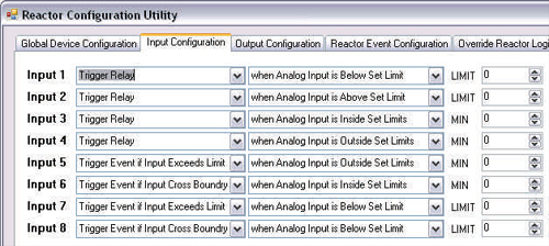
Every Reactor Controller continuously monitors 8 analog or contact closure inputs. Connect sensors operating from 0 to 5 VDC, switches, or dry contacts and define exactly how Reactor should respond.Each input can independently trigger relays, timers, or automation sequences, allowing a single controller to monitor multiple sensors simultaneously.
Precision Trigger Control
Reactor converts each 0 to 5 VDC input into 256 programmable trigger levels, allowing precise control over when events occur.Instead of simply reacting to ON and OFF signals, you can configure trigger points above, below, or within a specific sensor range. This provides exceptional flexibility for monitoring temperature, pressure, liquid level, light intensity, and countless other analog sensors.
USB Communications
The Reactor connects to your computer through USB and appears as a standard COM port, making configuration quick and reliable. USB drivers are included with the Base Station Software and are also available in the Resources section.After configuration is complete, the USB cable can be disconnected while Reactor continues operating autonomously.
Point-and-Click Configuration
Reactor Controllers are configured using the included Base Station Software. Simply choose how your sensors should respond, upload the configuration to the controller, and Reactor takes over. No programming required.
Base Station Reactor Configuration
"Configure to fit your application needs."
Build Automation Without Programming
The Reactor Controller is configured using the included Base Station Software, making it easy to build everything from simple relay triggers to sophisticated automation routines without writing a single line of code.Using a point-and-click interface, you can define how sensors trigger relays, create programmable time delays, build relay sequences, and configure advanced automation that continues running long after the computer has been disconnected.
Real-World Application
Temperature ControlA temperature sensor reaches 85°F. Reactor automatically starts an exhaust fan. When the temperature falls, a timer keeps the fan running for another 10 minutes before shutting it off.
Every Input Can Make a Decision
Each of the Reactor's eight inputs can monitor a sensor, switch, or contact closure and respond based on the conditions you define.
Configure an input to:
- Trigger above a sensor level
- Trigger below a sensor level
- Trigger within a specified range
- Trigger outside a specified range
- Activate a relay directly
- Start a timer
- Trigger another automation event
Real-World Application
Motion Activated LightingA motion sensor turns warehouse lighting on when someone enters the building. Reactor automatically turns the lights off five minutes after the last movement is detected, helping reduce energy costs.
Build Logic That Fits Your Application
Reactor separates inputs, events, and relays, giving you tremendous flexibility.
An input doesn't have to turn on a relay immediately.
Instead, an input can:
- Start a timer
- Increment a rotation counter
- Trigger another event
- Activate one or several relays
- Begin a sequence of operations
Real-World Application
Tank Level ControlA liquid level sensor reaches a programmed level and Reactor automatically starts a pump. When the tank is empty, Reactor turns the pump off, maintaining the desired water level without operator intervention.
Flexible Relay Control
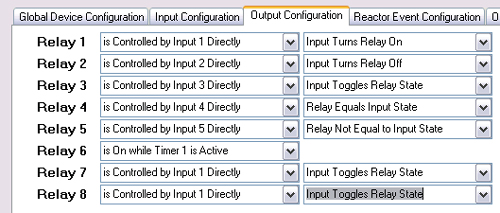 Every relay can respond to an input, timer, rotation counter, or automation event.
Configure relays to:
- Turn ON
- Turn OFF
- Toggle
- Follow the input state
- Operate opposite the input state
Relay Pros ProTip
Relay Logic AdditionNeed both automatic and manual control?
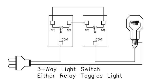
Use Reactor to operate a relay automatically from a sensor, then wire a standard wall switch using the 3-Way Relay Logic example. Now either the Reactor or the wall switch can turn the load ON or OFF independently.
It's a great way to combine automatic operation with convenient local control, giving you the best of both worlds.
Grow From Simple to Sophisticated
Start with a single sensor controlling one relay.Then expand to timers, relay sequencing, alternating equipment, and complex automation routines using Event Piping and internal events.
Whether your application requires a simple temperature-controlled fan or a multi-step automation process, Reactor grows with your requirements without requiring custom software development.
Real-World Application
Pump AlternationAlternate two pumps every time a tank fills. Reactor automatically rotates which pump starts first, balancing operating hours and extending equipment life.
Computer Control When You Need It
Although Reactor is designed to operate autonomously, a connected computer can temporarily take control at any time.Monitor sensor values, manually operate relays, trigger events, update configurations, or return control back to the Reactor's onboard logic whenever needed.
Real-World Application
Equipment CommissioningDuring installation, manually operate relays and monitor sensors from your computer. Once testing is complete, return control to Reactor's autonomous logic.
Configure Once. Operate Automatically.
Reactor's decision logic is stored directly on the controller. Once your configuration has been uploaded, the onboard processor continuously monitors sensor inputs and executes your programmed automation without requiring a connected computer.
Reactor Technical Specs
"From Sensor Input to Intelligent Relay Control"
How Reactor Makes Decisions
Reactor Controllers continuously monitor eight analog inputs and convert incoming voltages into digital values. The onboard processor continuously compares those values against your programmed conditions, then executes relay actions, timers, rotation counters, or event sequences. All decision making occurs locally on the controller, eliminating the need for a continuously connected computer.Input Voltage Changes
 Reactor analog inputs are designed to detect very small voltage changes with 8-bit resolution. In the case of a Reactor controller, analog inputs have an 8-bit resolution, meaning the voltage input (from 0 to 5VDC) is interpreted as a value from 0 to 255.
- For Example
- A voltage input of 0 Volts is interpreted as a value of 0
- A voltage input of 2.5 Volts is interpreted as a value of 128
- A voltage input of 5 Volts is interpreted as a value of 255
Instead of responding to only ON and OFF conditions, Reactor can react to 256 distinct sensor levels, allowing precise control of analog devices such as temperature, pressure, light, and liquid level sensors.
Trigger Logic
Reactor compares every sensor reading against user-defined trigger conditions. Instead of simply detecting whether an input is ON or OFF, Reactor can evaluate whether a sensor value is above, below, within, or outside a specified range before taking action.- Above a value
- Below a value
- Within a range
- Outside a range
Timers and Rotation Counters
Timers allow Reactor to delay relay activation, keep relays energized for a specific duration, or schedule actions after an event occurs. Up to eight independent timers can run simultaneously and may trigger additional events through Event Piping.Rotation Counters provide an easy way to alternate equipment, step through relay sequences, or distribute operating hours across multiple devices. Up to four rotation counters can operate in the background, making Reactor ideal for applications such as alternating pumps, compressors, or fans.
Event Piping
Event Piping allows one automation event to trigger another, making it possible to build sophisticated control sequences without programming.For example, an input can start a timer. When that timer expires, it can trigger a second timer, increment a rotation counter, or activate another event. By linking events together, Reactor can perform multi-step automation that would normally require a PLC or custom software.
Whether you're creating delayed actions, equipment sequencing, or layered automation routines, Event Piping gives Reactor the flexibility to handle surprisingly complex applications while remaining easy to configure through Base Station Software.
Real-World Application
Automatic Equipment StartupA pressure switch starts an exhaust fan immediately. Ten seconds later, Reactor starts a dust collector. After another delay, the production equipment is energized. Event Piping creates the entire startup sequence without requiring a PLC.
Local Decision Processing
Unlike PC-based automation systems, Reactor evaluates sensor inputs and executes relay logic directly on the controller.Because all decision making occurs locally, relay response times remain consistent even when a computer is disconnected. This improves reliability by eliminating the need for a continuously running PC, operating system updates, or background software during normal operation.
Unlike PC-based control systems, Reactor performs all automation locally on the controller. Your application continues running even after the computer has been disconnected.
Deterministic Operation
Once configured, Reactor performs the same programmed logic every time the specified input conditions occur. Since all automation executes on the controller itself, operation is predictable and repeatable without relying on Windows, background software, or network communications.Computer Override
Reactor gives you the best of both worlds. It can operate independently using its onboard decision logic, or a connected computer can temporarily take control whenever manual operation, testing, or monitoring is required.When a computer issues relay commands, those commands take priority over Reactor's autonomous logic. Individual relays can be configured to remain under Reactor control while others respond directly to the computer, providing exceptional flexibility for hybrid automation systems.
Reliable Sensor Control
Reactor boards are built for dependable, no-nonsense sensor control. You get industrial-grade hardware, the full sensor control, built-in analog inputs, and long relay life - without expansion complexity or unnecessary extras.
Reactor Board Features
"Designed for reliable automation - the hardware makes it happen"
Reactor Relay
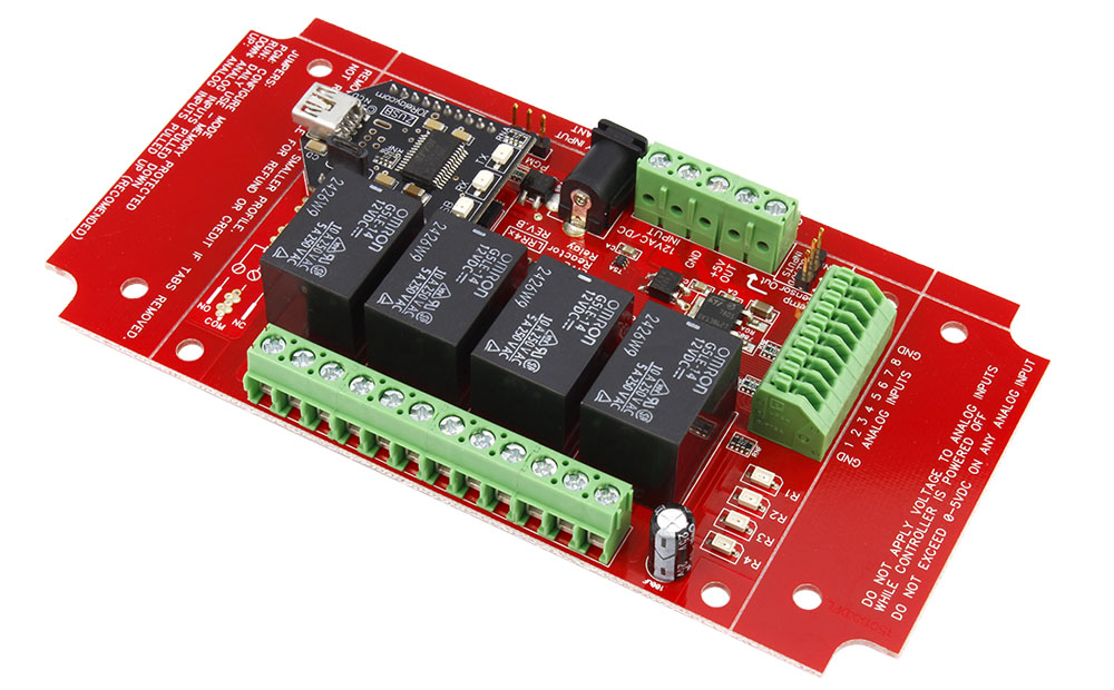
In this tab we'll take a look at the Reactor board design itself. The Reactor series controllers are machine manufactured for a highly accurate and reliable design. Fully tested before they leave the production facility each Reactor controller is ready to stand up to rigorous demands from heat, cold or vibration. The best test of all is the numerous boards in the field from customers all over the world in all sorts of conditions. Take it from us, these controllers will hold up!The Input Side
"Where Reactor gathers information."
Configure with USB. Operate Automatically
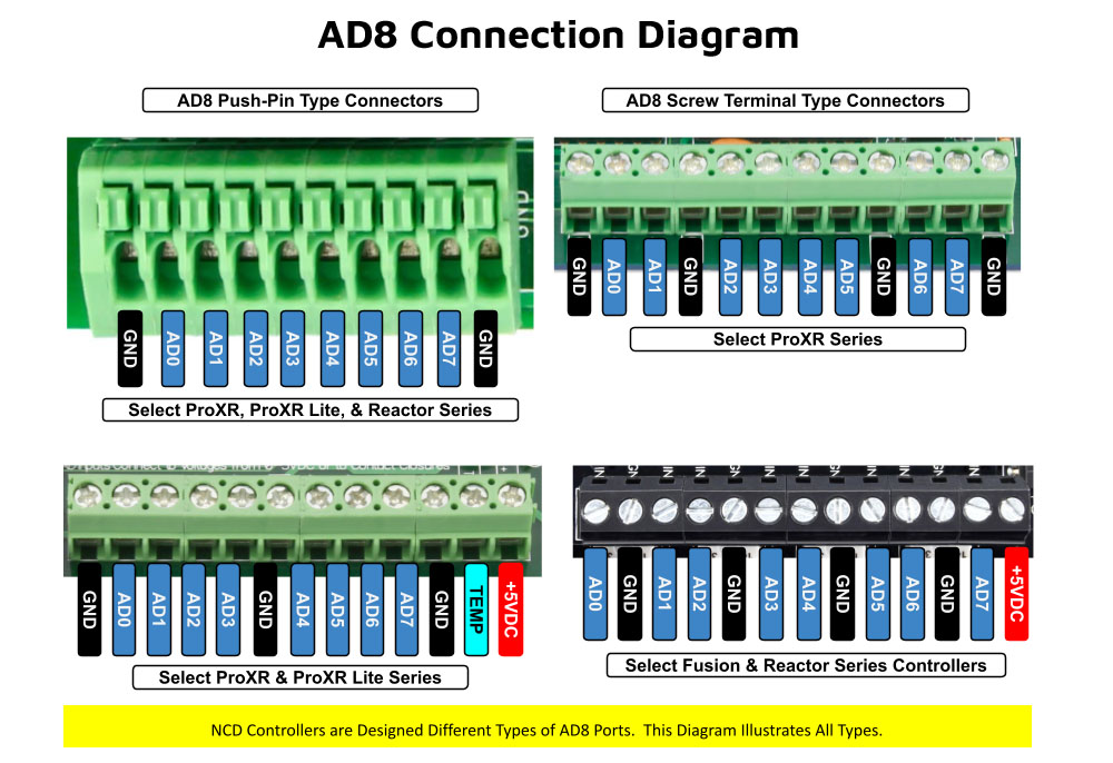 This controller includes eight channels of 8-bit sensor inputs capable of reading 0 - 5V DC signals. The inputs allow you to monitor external sensors or detect contact-closure inputs. Connect temperature sensors, light sensors, current sensors, buttons, switches, or any device that outputs a 0 - 5V signal or simple contact closure.
8 Analog Inputs
- 0-5VDC
- 8-bit (256 levels)
- Sensor or contact closure
- Common ground
- Constantly monitored
Analog Resolution
Every analog input can distinguish 256 different voltage levels, allowing Reactor to make decisions based on precise sensor values rather than simple ON/OFF signals.Analog inputs can accept voltages from 0 to 5VDC ONLY. Higher voltages and negative voltages will damage the Reactor controller. Improper use of these inputs can cause irreparable damage to the board.
The Output Side
"Where Reactor controls your equipment."
SPDT Relay Installed
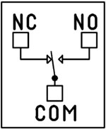 SPDT (Single Pole Double Throw) relays include three terminals: Common (COM), Normally Open (NO), and Normally Closed (NC)
- When the relay is off, COM is connected to NC.
- When the relay is energized, COM switches to NO.
2 Million+ Cycles
Reactor relays are built for longevity - expect years of reliable operation and millions of mechanical cycles. Every board ships with a 5-year warranty and 30-day money-back guarantee.Board Features
"What sets Reactor apart."
Break-A-Way Tabs for a Smaller Design
Need a smaller footprint? The Reactor PCB includes Break-A-Way Tabs, allowing the board to fit into optional undrilled enclosures or tight-space installations.
RoHS Compliant & Lead-Free
All ProXR Lite controllers are built with RoHS-compliant components and lead-free solder.Power & Protection
"Reliable Power = Reliable Switching"
Essential Power Requirements
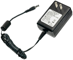 Clean, regulated power is critical.
A stable 12VDC supply ensures both the relay coils and onboard firmware operate correctly. Unstable or noisy power can cause improper switching or communication issues.
We recommend the PWR12-US (120VAC → 12VDC @ 1.25A) or our international supply with interchangeable adapters.
Learn More
Induction Suppression
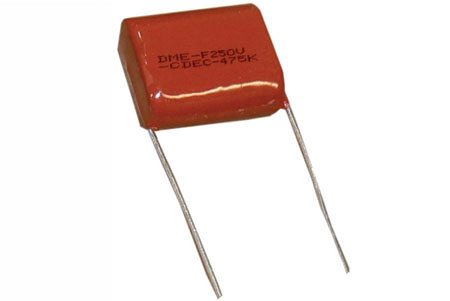 One of the most important parts of relay control - yet the most commonly overlooked - is inductive load protection.
Anything with a magnetic coil (motors, solenoids, transformers, etc.) generates high-voltage "kickback" when switched. Without a suppression capacitor, that spike can:
- Shorten relay lifespan
- Cause electrical noise that disrupts the microcontroller
- Trigger unexpected shutdowns
- Require power cycling to restore communication
Support & Ownership
"5-year warranty & no monthly subscriptions."
5-Year Warranty & Guarantee
Every Reactor controller is covered by:- 5-Year Functional Warranty
- 30-Day Money-Back Guarantee
- No Monthly Subscriptions
Shipping
All boards ship directly from our Missouri facility. Each unit is built and tested at the time of order - please allow 3 - 5 days for production. We ship primarily through UPS, but we're happy to use FedEx or DHL for international orders when you provide your account number. Questions? Call us at 800-960-4287 or email sales@relaypros.com.Hardware Built for Automation
Trigger relays with a sensor with and configure with included Base Station software. Here's a lists of great features: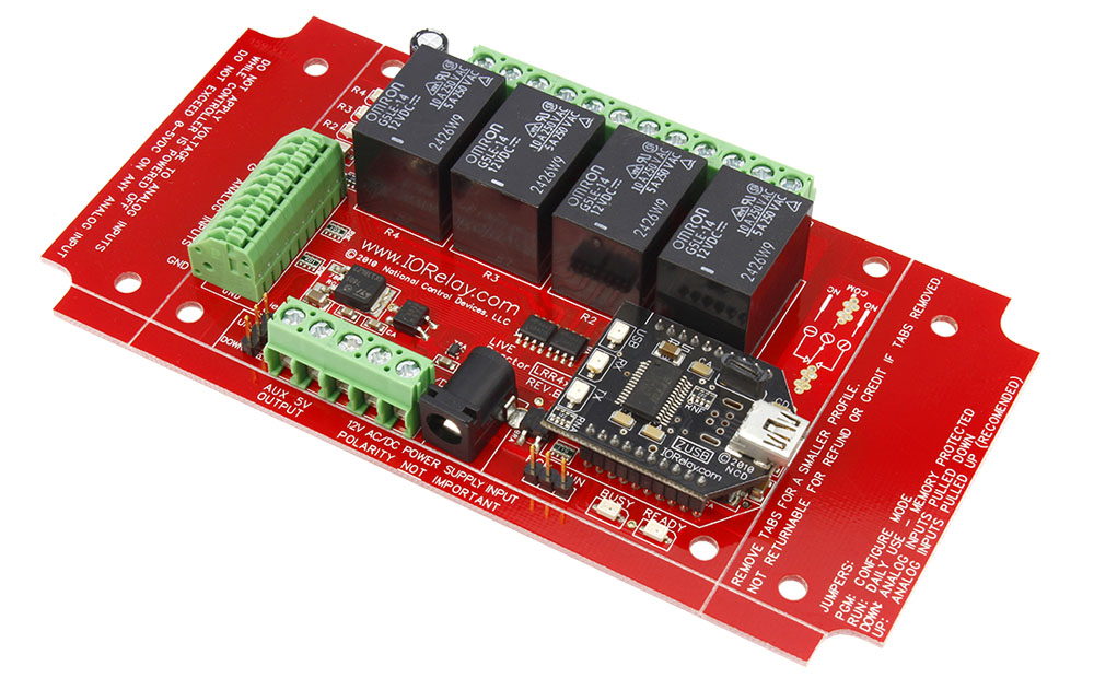
- User Friendly Software
- Point & Click Interface - No Programming Knowledge Required
- Override Sensor When Computer is Connected to Board
- Read Sensor Levels in Base Station
- Read Status of Relays in Base Station
- User Friendly Board Design
- 8 Analog Sensor Inputs Available (0 to 5 Volt Only)
- Break-A-Way Tabs lets you decide the board's size
- Screw terminal connections make connecting to the relays easy
Plan Your Power with Confidence
Get reliable performance every time! Use these real-world specs to build accurate power budgets, protect your board, and ensure every relay and module runs smoothly under any conditions.
Power & More
"Reliable Power = Reliable Switching"
Board Performance Ratings
This tab brings together the essential performance ratings you'll want to know for NCD SPDT Relay Controllers and their supported communication modules. You'll find practical electrical requirements, power consumption estimates, operating limits, relay timing details, and more-all based on typical 12VDC operation at 70°F (21°C). Think of it as a reliable snapshot of how our hardware behaves under real-world conditions. Because every installation is unique, some values are estimates and may evolve as designs and testing continue. Use this information as a planning tool to help you choose the right controller, build an accurate power budget, and understand the capabilities built into every NCD SPDT relay board.Powering from a Battery or Solar Panel?
NCD relay controllers are well-suited for battery-powered and solar-charged applications when operated within the recommended 10 - 15VDC range. This makes them ideal for remote, mobile, and off-grid installations using common 12V battery systems with solar charging. The power consumption data on this page helps you estimate runtime, size your battery, and avoid over-discharge. Staying within the voltage limits ensures stable, reliable operation in long-term battery and solar-powered setups.💡 Relay ProTip:
When powering a controller from a battery or solar power, keep voltage between 10-15VDC for reliable operation. Falling outside this range can cause unstable behavior or unexpected resets.
The SPDT Relay
SPDT (Single Pole Double Throw) relays include three terminals: Common (COM), Normally Open (NO), and Normally Closed (NC)
- When the relay is off, COM is connected to NC.
- When the relay is energized, COM switches to NO.
2 Million+ Cycles
ProXR relays are built for longevity - expect years of reliable operation. The SPDT relay is rated for millions of mechanical cycles. Every board ships with a 5-year warranty and 30-day money-back guarantee.SPDT Relay Board
SPDT Relay Controller Specifications
This table outlines key performance ratings for all NCD SPDT Relay Controllers, based on 12VDC operation at 70°F (21°C). Many values are estimated and may be updated over time. Some ratings reflect standard, out-of-the-box settings without performance optimizations applied.Processing times can vary depending on background services and the commands you use. Standby power values assume no communication module is installed and no relays are active. For a more accurate power estimate, be sure to include the consumption of any installed communications module and any energized relays.
| Specs of NCD SPDT Relay Boards | Minimum | Nominal | Maximum | Notes |
| Operational Voltages | 10VDC | 12VDC | 15VDC | |
| Standby Power Consumption | 35mA | 100mA | 200mA | No Active Relays, No Com Module |
| Relay Power Consumption | 28mA | 35mA | 60mA | Consumption of Each Activated Relay |
| Operational Temperature Range | -40°F (-40°C) | 70°F (21°C) | 185°F (85°C) | Theoretical Component Limits Shown |
| Storage Temperature Range | -67°F (-55°C) | 70°F (21°C) | 185°F (85°C) |
Theoretical Component Limits Shown |
| Operational Ambient Air Humidity | 0% | 50% | 70% | Non-Condensing Humidity Values Shown |
| Relay Activation Time | 4ms | 5ms | 10ms | Needs Further Validation |
| Relay Deactivation Time | 5mS | 10mS | 15mS | Needs Further Validation |
Communication Modules
Communication Module Specifications
This table provides a quick, clear overview of all NCD Communication Modules. While each module operates at 3.3VDC, the values shown here reflect the impact on a 12VDC master controller at 70°F (21°C). Use the maximum ratings for power-budget planning - they represent short-term peak consumption and may include estimated values that are updated as modules evolve.| Specs of NCD Communication Modules | Minimum | Nominal | Maximum | Notes |
| Operational Temperature Range | -40°F (-40°C) | 70°F (21°C) | 185°F (85°C) | Theoretical Component Limits Shown |
| Storage Temperature Range | -67°F (-55°C) | 70°F (21°C) | 185°F (85°C) | Theoretical Component Limits Shown |
| Operational Ambient Air Humidity | 0% | 50% | 70% | Non-Condensing Humidity Values Shown |
| USB Module Power Consumption | N/A | N/A | N/A |
USB Modules are Powered by the USB Port Do Not Consume Device Current |
| RS-232 Module Power Consumption | 10mA | 20mA |
|
|
| Ethernet Module Power Consumption | 58mA | 82mA | 100mA | |
| WiFi Bluetooth USB Module Power Consumption | 37mA | 50mA | 100mA | Up to 300 Foot Indoor Wireless Range, Unobstructed. Up to 50 Foot Range Through Walls |
| 900MHz Wireless Module Power Consumption | 13mA | 30mA | 50mA | Up to 1,000 Foot Indoor Wireless Range, up to 2 Mile Outdoor Wireless Range using Included Antennas. Up to 28 Miles Outdoor Wireless Range using High-Gain Antennas. |
| KFX Wireless Key Fob | 11mA | 15mA | 25mA | Up to 200 Feet Outdoor Wireless Range using 1, 2, 3, 4, or 5 Button Key Fobs. Up to 700 Feet Outdoor Wireless Range using 8-Button Remotes |
A/D Inputs
AD8 Analog Input Usage Notice
Analog inputs should never have voltage applied when the controller is powered down. If your application requires voltage to remain on an input, add a 220-ohm current-limiting resistor to each channel to protect the controller from damage. Keep all analog inputs within the 0 - 5VDC range - exceeding this limit can permanently damage the on-board CPU. Most inputs include a 10K pull-up or pull-down resistor to keep the line stable when unused, but note that this resistor may introduce a slight bias in readings for certain sensors.LRR410_USB Accessories
Power Supply Available
 The PWR12 is regulated power supply providing clean power necessary for
the performance of these boards. The PWR12 US power supply is a 120VAC to 12VDC 1.25A 60Hz regulated
power supply and it plugs into the barrel connector on the board. The output connector is a 2.1mm I.D. x 5.5mm
O.D. x 9.5mm R/A barrel connector.
The PWR12 is regulated power supply providing clean power necessary for
the performance of these boards. The PWR12 US power supply is a 120VAC to 12VDC 1.25A 60Hz regulated
power supply and it plugs into the barrel connector on the board. The output connector is a 2.1mm I.D. x 5.5mm
O.D. x 9.5mm R/A barrel connector.
Click Here for More
Enclosure Available
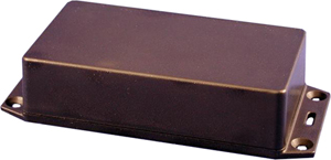 The DFL Enclosure is an undrilled, non-waterproof enclosure and is available at checkout for this controller.
Spec Sheet and Drawings:
DFL Spec Sheet
CAD Drawing: DFL CAD Drawing
3D Model: DFL_3D
Induction Suppression
Controlling
an inductive load using our relay controllers requires the use of induction suppression capacitors. The purpose of this capacitor
is to absorb the high voltages generated by inductive loads, blocking them from the contacts of the relay. Without this capacitor,
the lifespan of the relay will be greatly reduced. Induction can be so severe that it electrically interferes with the microprocessor
logic of our controllers, causing relay banks to shut themselves down unexpectedly.
Click Here for More
Base Station
 Reactor boards are configured
using Base Station Software (a free download). Using a point-and-click interface for configuration means you can accomplish automation tasks in minutes.
There are no programming languages to learn.
Reactor boards are configured
using Base Station Software (a free download). Using a point-and-click interface for configuration means you can accomplish automation tasks in minutes.
There are no programming languages to learn. Click for more on Base Station.
Relay Wiring Made Simple
From simple on/off switching to advanced AND/OR logic, these examples show exactly how to connect your relays for real-world applications. Learn the tricks to control lights, motors, sensors, and more with confidence.
Get a printout of this page
Relay Logic
"Using a light as an example load, let's wire to the board"
Relay Wiring Samples
This page provides simple examples showing how to wire a single relay - or multiple relays - for common switching applications. We use a light as the example load, but you can substitute a gate controller, security panel input, dry contact device, motor trigger, or most other switched loads. These wiring samples demonstrate different ways to connect relays to achieve the switching behavior you need.Relay Types
SPDT Relay
SPDT (Single Pole Double Throw) relays include three terminals: Common (COM), Normally Open (NO), and Normally Closed (NC).
- When the relay is off, COM is connected to NC.
- When the relay is energized, COM switches to NO.
Your load can be wired to either the NO or NC terminal depending on whether you want the device to turn on when the relay activates or when it releases. Examples below demonstrate both wiring methods. The SPDT relays offered on this site are 5-Amp, 10-Amp and 20-Amp models.
SPST Relay
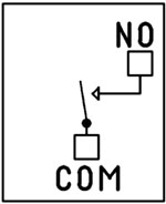
SPST (Single Pole Single Throw) relays provide two terminals: Common (COM) and Normally Open (NO).
When the relay coil is energized, COM connects to NO to power the load. The only SPST relays offered on this site are our 30-Amp models. All SPDT examples shown on this page apply to these relays as long as the example does not require a Normally Closed terminal.
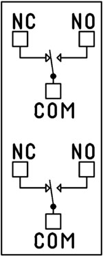
DPDT Relay
A DPDT (Double Pole Double Throw) relay contains two SPDT switches that operate together.
- Each side includes its own COM, NO, and NC terminals.
- Both internal switches change state at the same time.
This allows you to control two independent circuits with one relay. Wiring for each side of a DPDT relay follows the same rules as an SPDT relay, so the examples on this page apply directly. We offer the DPDT relays in 1-Amp, 3-Amp and 5-Amp models on ProXR boards starting at 8 relays.
Relay Grouping
Relay Grouping in the ProXR Command Set lets you combine individual relays to function like a DPDT relay using separate channels. This is ideal when you need to control multiple relays simultaneously or exceed the 5-Amp switching limit of our standard DPDT relays.Relay Logic Examples
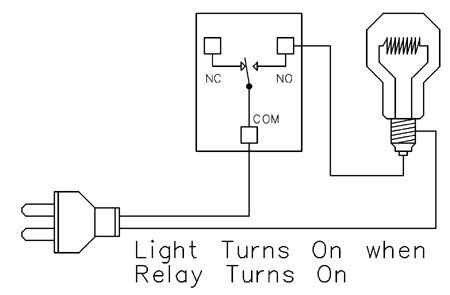
Example 1 - Simple Off/On Control
This example shows the most basic way to use a relay to switch a device such as a light. When the relay energizes, its NO (Normally Open) contact closes to COM (Common), completing the circuit and turning the light on.Only a single power wire is switched in this setup, making it the simplest method for controlling a light - or any device - using a relay.
Use this example for switching a light or any device you want to power only when the relay is on.
Example 2 - Simple On/Off (Using NC Contact)
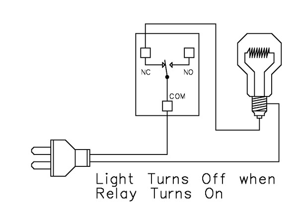
This wiring method keeps the light on by default. The relay switches a single power wire through the COM (Common) and NC (Normally Closed) terminals.When the relay is not energized, the NC contact is closed to COM and the light remains on.
When the relay energizes, the NC contact opens, interrupting power and turning the light off.
This approach is ideal for devices that stay on most of the time, reducing relay wear since it doesn't need to remain energized to keep the device powered. It's also a useful method for power-cycling equipment - energizing the relay momentarily will turn the device off.
💡 Relay Pros ProTip:
For devices that stay on most of the time, use the NC contact. This reduces relay wear and extends the life of both the relay and your power supply.
Example 3 - AND Logic Using Two Relays
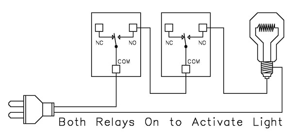 This example shows how two relays can work together so a light turns on only when both relays are energized. This creates an AND Logic condition:
Relay 1 AND Relay 2 must be on for the light to receive power.
A single power wire is switched, but it must pass through both relay contacts before reaching the light. This setup is ideal when two conditions must be met at the same time - such as requiring input from multiple sensors or system parameters.
MirC/MirX/MirM Users:
This wiring requires two contact closure inputs on the sender board before the receiver's relay activates. Use this approach when two independent outputs must close before turning on the light.For example, a light could turn on only when:
1. A light sensor detects it's dark AND
2. A motion sensor detects activity in the room
Example 4 - AND Logic Using Three Relays
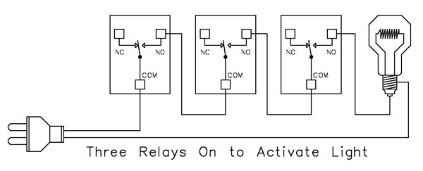 This example expands on the previous AND Logic concept. Here, the light will turn on only when all three relays are energized:
Relay 1 AND Relay 2 AND Relay 3 must be on for power to reach the light.
A single power wire is routed through all three relay contacts. Wiring from the NO (Normally Open) of Relay 1 to the COM (Common) of Relay 2, then from the NO of Relay 2 to the COM of Relay 3, creates a series path that requires every relay to energize before the light can activate.
This method can be scaled easily - just continue wiring NO of each relay to the COM of the next relay. Add as many relays as needed to meet your logic or safety requirements.
Example 5 - AND/OR Logic with Override
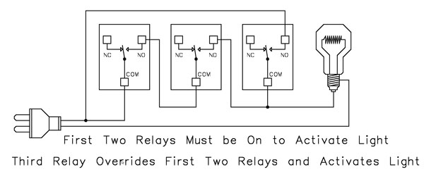 This example demonstrates a combined AND/OR logic setup. The light will turn on when:
- Relay 1 AND Relay 2 are both energized OR Relay 3 is energized (override)
- For example:
- Relay 1 = night/day sensor
- Relay 2 = motion sensor
- Relay 3 = manual override (local switch)
A/D Board Users:
The Relay Activator function on any A/D board or ProXR Lite board lets you connect a button or switch to any A/D input. This input can then control the override relay, giving you a convenient local button to manually override the first two relays.MirC/MirX/MirM Users:
Add a manual button or switch to trigger the third relay when you need direct control instead of sensor-driven control.Reactor Users:
A local button or switch can be wired to the third relay input to provide a manual override for sensor-based logic.Example 6 - OR Logic (Either Relay Activates)
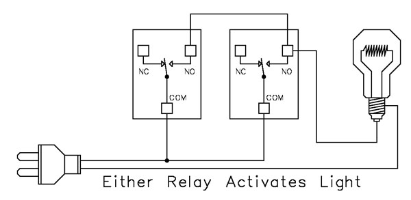 This example demonstrates OR Logic - the light will turn on when either relay is energized. Only one power wire is switched, but it can pass through Relay 1 or Relay 2 to reach the light.
- If Relay 1 activates, the light turns on
- If Relay 2 activates, the light turns on
- If both activate, the light remains on
- A timer controlling one relay, with a manual or secondary control for the other.
- Two sensors where either condition (motion detected or low light, for example) should activate the light.
A/D Board Users:
The Relay Activator function on any A/D board or ProXR Lite board lets you connect a button or switch to any A/D input. This input can then be used as a manual control of the relay.MirC/MirX Users:
Wire two contact closure inputs into the sender board - either input can trigger the receiver relay to control the light.Reactor Users:
Configure one relay for automatic sensor control and a second relay for manual push-button operation. Wire both relay outputs using OR Logic so either control method can activate the same light.Example 7 - 3-Way Switch (Relay-Based 3-Way Control)
This example shows how to create a 3-way light switch setup using relays. A traditional 3-way circuit allows two switches to control the same light from different locations. In this wiring sample, each physical switch is replaced by a relay - but the operation is the same.
Only one power wire is switched, and the relays toggle the light depending on their current state.
- Activating either relay will toggle the light
- Activating both relays at the same time has the same effect as flipping both switches at once
Example 8 - DC Motor Direction Control
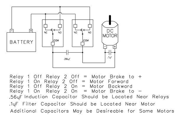 This example demonstrates how to control the direction of a DC motor using two relays. By changing how the motor's leads connect to power, you can run the motor forward, reverse, or place it in a brake state. Braking is achieved by tying both motor terminals to the same power connection, which stops rotation through Faraday's Law.
- Relay Operation Summary
- Relay 1 Off / Relay 2 Off → Motor Brake to +
- Relay 1 On / Relay 2 Off → Motor Forward
- Relay 1 Off / Relay 2 On → Motor Reverse
- Relay 1 On / Relay 2 On → Motor Brake to -
- The induction suppression capacitor prevents the relay from shutting off due to motor back-EMF
- The 0.1µF filter capacitor reduces electrical noise, especially useful when powering sensitive electronics such as radios or amplifiers.
- Capacitor Placement
- Place the induction suppression capacitor near the relays
- Place the filter capacitor near the motor
- Additional capacitors may be needed for certain motors
Motors draw significantly more current at startup than during continuous operation - often 2-3 times their rated running current. For example, a motor rated at 5A (125VAC) may require 10-15A to begin turning. Always select a relay that exceeds the motor's initial inrush current, not just its running current. In this case, a 20-30A relay provides optimal performance and longevity.
💡 Relay Pros ProTip:
Motors and inductive loads often draw 2-3x their rated current at startup. Always choose a relay that exceeds the motor's inrush current, not just its running current.
Protect Against Inductive Spikes
Motors, solenoids, contactors and other inductive loads can generate voltage spikes every time they switch on. For just a few dollars, suppression capacitors can help protect relay contacts and extend the life of your control system.
Simple to install and highly recommended for inductive loads, capacitors are one of the easiest ways to improve long-term system reliability.
Induction Suppression
Handling Inductive Loads (Why It Matters)
Inductive loads are anything with a magnetic coil - motors, solenoids, transformers, mag locks, door strikes, etc. These devices generate dangerous voltage spikes when switched on and off.Those spikes can:
- Destroy relay contacts prematurely
- Cause unexpected controller resets
- Knock USB devices offline
- Damage the board's power regulation circuitry
💡 Relay Pros ProTip:
Many customers skip suppression because it seems complicated. In reality, adding a suppression capacitor typically requires only two connection points and can dramatically reduce relay contact wear when switching motors, solenoids and contactors.Why You Need a Capacitor
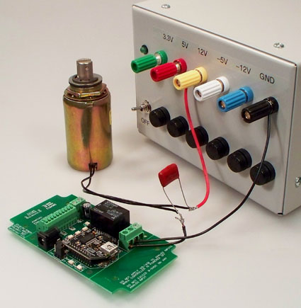 Every time an inductive device switches on, it releases a burst of high-voltage energy.
A suppression capacitor:
- Absorbs these spikes before they reach your relay
- Protects relay contacts from arcing
- Prevents interference with the microcontroller logic
- Helps maintain stable USB or serial communication
Resistive Loads Don't Need Suppression
If you're switching a purely resistive device, such as:- Incandescent/LED lighting
- Heating elements without fans
- Basic resistive appliances
- Using Relay as Dry Contact Output
Choosing the Right Capacitor
 It's simple:
Choose a capacitor with a voltage rating equal to or higher than the voltage of the device you're switching.
Example:
- Switching a 120VAC motor → Use a capacitor rated for 120VAC or higher
- Switching a 24VDC solenoid → Use a capacitor rated for 24VDC or higher
Suppression capacitors can retain a charge for a short period after power is removed. Always discharge capacitors safely before handling.
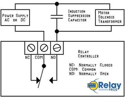
Easy Installation
Installing a suppression capacitor is straightforward:- Mount it as close to the relay as possible
- Connect it in parallel with the inductive load
- Polarity doesn't matter - capacitors used for suppression are not polarized
- Works with both AC and DC loads
Don't Share Power Supplies with Inductive Loads
Your controller must be powered by a clean, regulated power supply.Do not share the same power supply with:
- DC motors
- High-power solenoids
- Any heavy inductive device
The only exception: battery-powered systems (like automotive) where the battery naturally absorbs induction spikes.
Important Note for USB Users
USB is extremely sensitive to electrical noise. An inductive spike can cause the PC's motherboard to drop the USB port entirely.That means:
- Your controller disappears from the OS
- Your application loses communication
- You must unplug and reconnect the board