8-Channel Programmable Potentiometer with Ethernet Interface
ZPOT8PROXR_ETHERNET
Resistance Output
The ZPOT8ProXR_ETHERNET allows software control of up to 8 digital potentiometers, each with 256 programmable positions. Simply send a command to adjust the wiper position and change the resistance value electronically, eliminating the need for manual adjustment.Each potentiometer includes three connections: A, Wiper, and B. As the wiper moves toward terminal A, the resistance between A and the wiper decreases while the resistance between the wiper and B increases. Moving the wiper toward terminal B produces the opposite effect.
Potentiometer channels may be adjusted individually or multiple channels can be updated simultaneously.
Ethernet Potentiometer
The ZPOT8ProXR_ETHERNET combines NCD's programmable digital potentiometer technology with an integrated Ethernet interface for network-based control. Connect the controller to your network using a standard CAT5 cable and send commands from computers, PLCs, custom software, web applications, or remote systems to adjust potentiometer values electronically.The onboard NCD5500 Gen3 Ethernet module obtains an IP address from your network, allowing potentiometer channels to be controlled from anywhere on the local network. With proper network configuration, the controller can also be accessed remotely over the Internet.
Designed specifically for NCD controllers, the NCD5500 Ethernet interface provides reliable communication and seamless integration with NCD's command protocol. Simply open a TCP connection and send commands to adjust up to 256 potentiometer channels when expansion modules are installed.

USB Potentiometer at a Glance
- 8-Channel Digital Potentiometer
- 256 Tap Positions Per Potentiometer
- Available in 10kΩ, 50kΩ, and 100kΩ Versions
- Up to 1mA Wiper Current Per Channel
- Expandable to 256 Pots Using the UXP Expansion
- Control Relays Using the XR Expansion Port
- 12 Guage Solid Core Wire Capacity
- Operating Temperature: -40°C to +85°C - 3rd Generation Ethernet
- Supports DHCP & Fixed IP Address
- Web Interface for Configuration Settings
- Programmable TCP Port and IP Address
- Windows App for Configuration and Recovery
)
Important: Resistance Output Only
These controllers provide a programmable resistance output, not a programmable voltage output. They are designed for applications operating between 0 and 5VDC with a maximum 1mA wiper current per channel. Exceeding these limits can permanently damage the potentiometer.
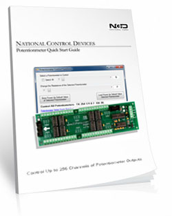
Programmable Potentiometer
"Electronic Resistance Control Through Simple Commands"
Digital Potentiomer
Replace manual potentiometer adjustments with software control. NCD's Programmable Digital Potentiometer allows your application to electronically adjust resistance values by simply sending commands from a computer, PLC, microcontroller, or custom software.Each controller provides 8 independent digital potentiometers with 256 programmable tap positions per channel and is available in 10kΩ, 50kΩ, and 100kΩ versions. Individual channels can be adjusted independently or multiple channels can be updated simultaneously using the same simple command set used throughout the ProXR product family.
How It Works
Each potentiometer provides three terminals: A, Wiper, and B.Sending a lower value moves the wiper toward terminal A, decreasing the resistance between A and the wiper while increasing the resistance between he wiper and B.
Sending a higher value moves the wiper toward terminal B, decreasing the resistance between the wiper and B while increasing the resistance between A and the wiper.
The first 32 potentiometer channels can store a programmable startup position, allowing your application to automatically restore critical resistance values after power is applied.
Resistance Output Only
This board provides a programmable resistance output, not a programmable voltage output. It is designed for applications operating between 0 and 5VDC with a maximum 1mA wiper current per channel. Exceeding these limits may permanently damage the potentiometers.Choosing the Right Resistance Value
Digital potentiometers are available in 10kΩ, 50kΩ, and 100kΩ versions. The resistance value you select should match the requirements of the circuit you are replacing or designing.- 10kΩ is the most common choice and works well for many signal conditioning, amplifier, and general-purpose control applications.
- 50kΩ is often selected when a higher resistance range is needed while maintaining moderate current flow.
- 100kΩ is best suited for high-impedance circuits where very little current is required.
💡 Relay Pros ProTip:
If you're selecting a programmable potentiometer to replace a manual potentiometer, simply choose the same resistance value as the component you're replacing.
Software Controlled Resistance
Adjust one potentiometer or every potentiometer with simple serial commands. The POT Command Set provides precise electronic control over resistance values without manual adjustment.Whether controlling a single channel or a fully expanded system, the command structure remains consistent, making it easy to integrate with custom software, automation systems, PLCs, and NCD Base Station Software.
Expand as Your Application Grows
Built on NCD's proven ProXR platform, the controller is designed to grow with your application.The integrated UXP Expansion Port supports expansion up to 256 programmable potentiometers, while the XR Expansion Port allows NCD relay expansion boards to be added to the same system. This makes it possible to combine programmable resistance control and relay control using a single controller architecture.
The ProXR Command Set
Simple Serial Commands. Serious Control.
The ProXR family of controllers is driven by a powerful, low-level serial command set. You send a short numeric or Hex command to the board - and the board responds immediately.This design keeps your software fast, reliable, and easy to integrate into almost any platform, from small scripts to full automation systems.
How to Send Commands
You can send commands as:
- Decimal byte values
- Hex byte values
What a Command Looks Like
This command will set a single Potentiometer to a specified value where POT is the channel number and value is the new value of the potentiometer:254 170 0-255(Channel Number) 0-255(Value) - Set specific POTs value
0xFE 0xAA 0x00-0xFF 0x00-0xFF - If you require Hex
The controller processes the command and returns a confirmation byte 85 (0x55 Hex) when the operation completes.
Base Station Compatible
NCD's Base Station Software provides a simple point-and-click interface for learning the command structure, testing communications, and controlling potentiometer outputs before writing software.It is an excellent development tool for evaluating hardware and generating the commands used in your own applications.
💡 Relay Pros Pro Tip:
Let Base Station Show You the Command! Base Station software can show you the exact command being sent to the controller. When you control the potentiometers using the point-and-click interface - Base Station displays the actual command being transmitted to the board.
This is extremely useful for programmers. You can perform the function you want in your application and instantly see the decimal or hexadecimal command - the same command you'll use in your programming.
5-Yeary Warranty & Guarantee
Every potentiometer is covered by:- 5-Year Functional Warranty
- 30-Day Money-Back Guarantee
Essential Power Requirements
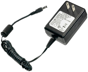 Clean, regulated power is critical.
A stable 12VDC supply ensures both the inputs and onboard firmware operate correctly. Unstable or noisy power can cause improper reading or communication issues.
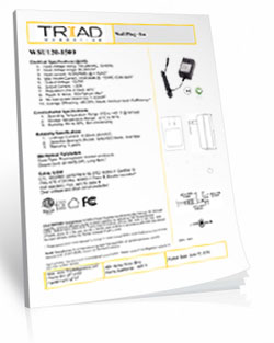
We recommend the PWR12-US (120VAC → 12VDC @ 1.25A) or our international supply with interchangeable adapters.
Learn More
Shipping
All boards ship directly from our Missouri facility. Each unit is built and tested at the time of order - please allow 3 - 5 days for production. We ship primarily through UPS, but we're happy to use FedEx or DHL for international orders when you provide your account number. Questions? Call us at 800-960-4287 or email sales@relaypros.com.Reliable Control Over Ethernet
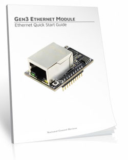
Bring NCD controllers onto your Ethernet network with dependable, plug-and-play control. The Gen3 Ethernet module delivers fast TCP/IP communication, easy web-based setup, and seamless Base Station compatibility - ideal for stable, always-on relay control.
Gen3 Ethernet Relay
"The Gen3 module delivers stable TCP/IP communication"
ZPOT8PROXR_ETHERNET - Gen3 Relay Control
Meet the NCD5500 Ethernet-to-Serial Converter, NCD's 3rd-generation Ethernet module designed for exceptional reliability, ease of use, and lower cost. This modular interface brings the entire line of NCD Industrial Devices onto your Ethernet network with plug-and-play simplicity.The NCD5500 works seamlessly with Base Station, making IP discovery and configuration fast and simple.
💡 Relay Pros ProTip:
Ethernet modules must connect to a router or network switch to receive an IP address. Plugging the module directly into a computer's Ethernet port will not establish communication.Ethernet to Serial Communications Module
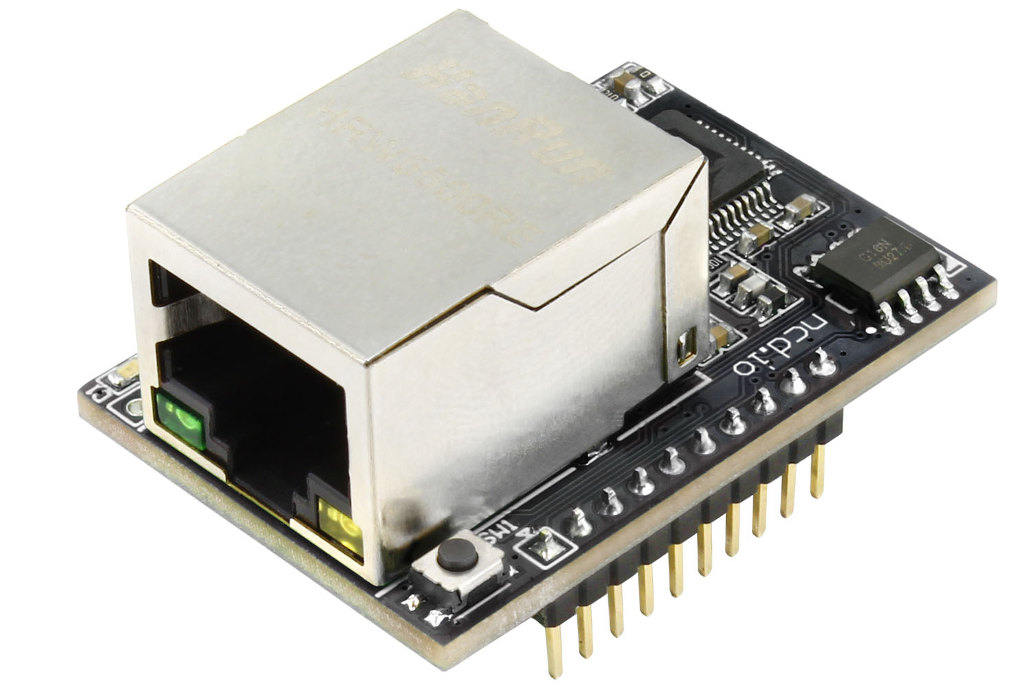 The Gen3 module converts TCP packets to serial data (and back again) for smooth, real-time control.
- Features include:
- Auto Socket Control - Choose to close the socket after a programmable timeout or keep the connection open
- Connection Status LED - A blue LED indicates an active socket connection
- Flexible Baud Rates - Adjustable from 9600 to 115.2K, using the default TCP port 2101
- Network Options - Supports both Static IP and DHCP
- One-Button Recovery - Restore factory defaults instantly with a simple button press
DHCP and Static IP Addresses
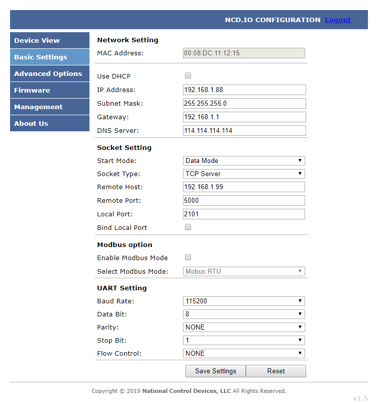 This module supports both DHCP and Static IP addressing.
For the most reliable remote access, we recommend using a Static IP Address once you are comfortable with the network configuration. This ensures consistent communication and predictable device access.
TCP/IP Communications
The primary communication method is a standard TCP Socket. This creates a bi-directional connection, allowing your computer or control system to send commands and immediately receive responses through the same socket - fast, robust, and ideal for relay control applications.3rd Generation Hardware
The latest hardware represents a major leap forward in reliability, usability, and cost efficiency.- Key improvements include:
- Lower overall cost compared to previous generations
- Enhanced recovery options
- Web-based configuration UI
- Windows utility for discovering devices with unknown IP addresses
- Firmware upgrade support for feature updates and improvements
Password Protection
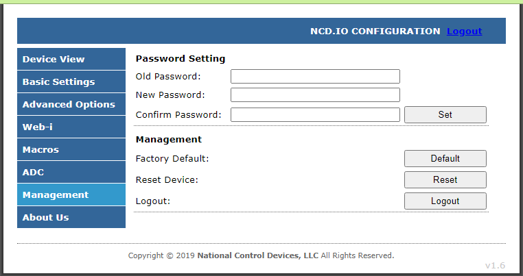 Password protection is built in.
Under the management tab, users can assign a password for added security and access control.
Default web-page login password: admin (user-changeable).
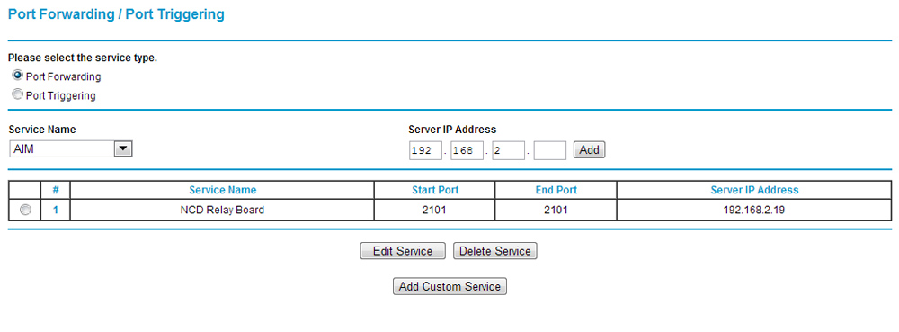
Port Forwarding
To access the module from outside your Local Area Network, Port Forwarding is required.Your router forwards incoming requests on a specific port (e.g., 2101) to the device's local IP address.
Example:
A router is configured to forward port 2101 to 92.168.2.19:2101. Any external request to port 2101 is automatically routed to the module. Without this rule, the router would not know where to send the request, and the connection would fail.
Note: Port Forwarding is not needed for communication within your LAN.
For step-by-step instructions for virtually any router, visit https://portforward.com/ .
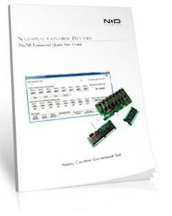
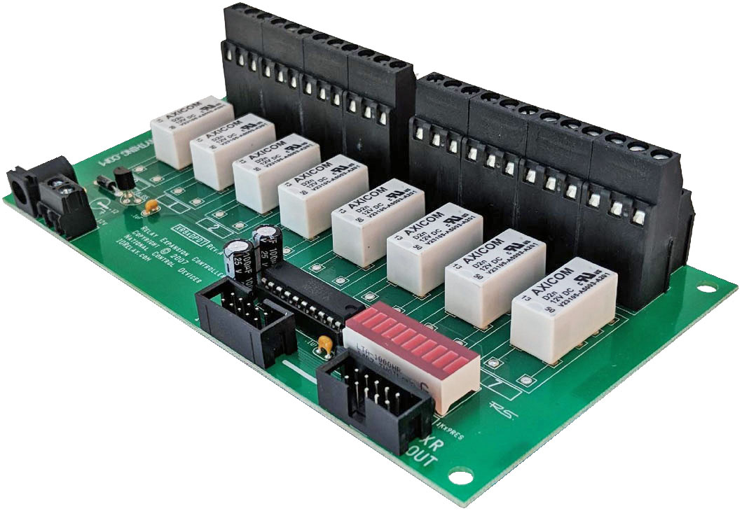
ProXR Expansion Board
Expansion Boards plug into the XR Expansion Port on any ProXR, Taralist or Potentiometer Board to add more relays. Expansion boards can be daisy chained together to add up to 256 relays as needed.
The XR Expansion Port
"Running out of relays? Just plug in more!"
Add Relays as Your Needs Grow
ProXR Controllers were built with relay expansion in mind. The XR Expansion Port lets you add banks of external relays to any ProXR or Taralist board equipped with an XR Expansion port. Expansion boards can be added at any time as your system grows, up to a maximum of 256 total relays.As expansion boards are added, additional relay banks become available automatically. Simply add another expansion board whenever you need more relays.
Relay Banks - How Large Systems Stay Simple
Each bank contains:
- Relay 1 through Relay 8
For example:
- An 8-relay controller uses one bank
- A 32-relay controller uses four banks
- A 64-relay setup uses eight banks
- Select a bank
- Send simple relay commands within that bank
Linking XR Expansion Boards Together
XR Expansion Boards include both an XR Input and XR Output connector. Connect the XR Output on your ProXR controller to the XR Input on the first expansion board. To add more relays, connect the XR Output of one expansion board to the XR Input of the next board in the chain.You can mix and match different relay types on expansion boards to match your application. A 6" expansion cable is included with each expansion board.
For best reliability, keep all expansion cabling as short as possible. Maximum expansion length and total relay count depend on your installation, electrical noise, and overall cable length. For best compatibility, the combined length of the controller, expansion boards, and cables should not exceed 1-2 meters.
Mix & Match
Expansion boards do not need to match the relay type or amperage of the main controller or other expansion boards. Mix and match expansion boards to get the exact relay types and current ratings your application requires.💡 Relay Pros Pro Tip:
You can mix and match relay types and amperages to dial in exactly what your application requires - for example, adding a bank of DPDT relays when all the other boards have SPDT relays. This gives you ultimate flexibility as your system grows.
Will Not Operate Independently
This Expansion Board gets it's commands from the main ProXR, Taralist or Potentiometer board and will not operate independently. This board MUST be plugged into a ProXR or Taralist board to operate and will not function on it's own.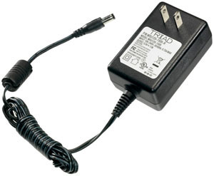
Essential Power Requirements
All XR expansion boards require their own 12 VDC power source. A regulated 12 VDC supply must be connected directly to each expansion board for proper operation.We offer a compatible wall-plug power supply at checkout, or you may use your own regulated 12 VDC supply. Learn More
Maximum Relay Rating Notes
ProXR is capable of expanding to an absolute maximum of 256 Relays. In some cases, it may not be possible to control all 256 relays, particularly in applications where high noise levels may be involved. Experimentation may be required, as it is not possible for us to guarantee all users will be able to utilize all 256 relays in every application. Noise tends to accumulate when several expansions are connected together. For best results, the XR expansion cables must be as short as possible.
RoHS Compliant
Expansion boards are led free and RoHS Compliant. If your requirements are for RoHS compliant parts every expansion board is manufactured with RoHS compliant led free parts and solder.2-Million Cycles
 XR Expansion Boards are designed for long life just as the ProXR boards, you should expect to get years of service from expansion board and literally 2-million cycles from the relays on board. With a 5-year warranty and a money back guarantee add more relays anytime the need arises!
 Relay Expansion Videos
Accessories
Power Supply Available
 Reliable Power Means
Reliable Switching
The PWR12 is regulated power supply providing clean power necessary for the performance of these boards. The PWR12 US power supply is a 120VAC to 12VDC 1.25A 60Hz regulated power supply and it plugs into the barrel connector on the board. The output connector is a 2.1mm I.D. x 5.5mm O.D. x 9.5mm R/A barrel connector.