Base Station Software
basestation
Base Station Software
Base Station Software is our reference tool for designing and testing all currently manufactured NCD Devices. Base Station will assist you in learning how any NCD device functions and will provide valuable diagnostic tools to help determine if your controller is functioning as designed. Base Station software exercises every supported feature of every supported device. Base Station Software was designed to help you learn the ProXR command set. Explore ProXR features using our Graphical User Interface. Watch data bytes flow to and from the board, so you easily understand the command execution process. There is no faster or easier way to learn how to automate than Base Station, it is designed to work with our complete array of communication modules, including Wireless, Ethernet, USB, RS-232, and more. You only need a Windows 8 or 10 Computer to Run Base Station, no other relay control board even comes close to offering this type of software!
- OVERVIEW
- Key Fob Setup
- AD8 Command Set
- Taralist Setup
- Reactor Setup
- Base Station
- ProXR Config
- Data Sheets
Base Station Compatible Boards
- All R1x/R2x Series Controllers
- All R4x/R8xPro Series Controllers
- All ProXR/ProXR Lite Series Controllers
- All KFX Key Fob Boards
- All Reactor Series Controllers
- All Taralist Series (Generation 1 and 2)
- All PWM8x Series Controllers
- Fusion Series Controllers
Buttons are Fully Configurable
Assign each button to a different relay, control the same relay with multiple buttons or create dedicated ON and OFF buttons for equipment that requires predictable operation.
This flexibility allows the system to be tailored to your application rather than forcing your application to fit a fixed button layout.
Base Station Key Fob Configuration
"Want it ready to go? We can pre-program your board before it ships."
Key Fob Configuration
The FX Receiver Module is configured using Base Station Software (free download). During setup, the module simply plugs into the ZIGMO Configuration Board. One ZIGMO is all you eed - no matter how many KFX Receivers you plan to configure.The ZIGMO serves as the communication bridge between your computer and the KFX Module, allowing you to set Baud Rate and define the Data Bytes sent for each key fob button press. The ZIGMO is included with the KFX Configuration Kit and is available at checkout.
Free Setup Software
Your board can ship preconfigured with toggle or momentary operation, Timers or grouping at no charge.For custom commands, use the Key Fob Configuration Kit and Base Station Software to program the KFX Module. After configuration, the module is placed back into your board and is ready to transmit your programmed commands each time a button is pressed.
💡 Relay Pros ProTip:
Key Fob Relay boards can be configured for timed relay operation, allowing relays to automatically turn off after a preset interval. We can preconfigure these settings before shipment, but purchasing a ZigMo Configuration Kit gives you the flexibility to make timing adjustments yourself whenever application requirements change.
ZigMo Configuration Kit
 KFX Receiver Modules are configured through Base Station Software and must be plugged into a ZIGMO Configuration Board during setup. The KFX Module is only installed in the Configuration Kit during setup - after that, it goes right back into your board. Only one ZIGMO is required no matter how many receivers you use.
The ZIGMO provides the connection between your computer and the KFX Module, allowing you to set Baud Rate, define Data Bytes, and customize the actions for each button press.
The ZIGMO is included in the KFX Integration Kit and available during checkout.
Configuring the Buttons
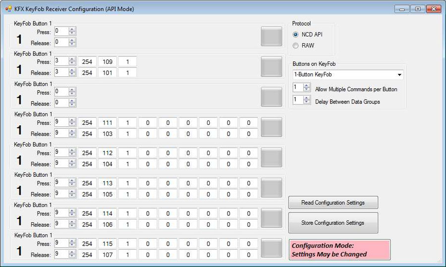 When you program a button, you're configuring the command the KFX Module will send to the board when that button is pressed. Using Base Station Software, you can assign simple toggle actions or advanced commands with delays, pulse patterns, or timed operations.
The KFX Module supports both button-press and button-release events for even greater flexibility.
Common Commands
Here's a brief list of some of the more common commands used when a button is pushed on the key fob.- Toggle and Momentary Commands
- Turn Off All Relays Then Turn On a Specific Relay
- Relay Timers: Relay Energized for a Specific Time
- Relay Pulse Commands
- Relay Grouping: Controlling Multiple Relays Together
- Relay Flashing Commands
KFX Module
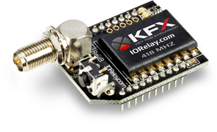 Every Key Fob Relay board is equipped with a KFX Communications Module, adding full wireless key fob capabilities. The module is powered directly from the board.
The board itself requires 12VDC, which can be hardwired or supplied using an optional wall-wart power supply available at checkout.
Data Sheets & Quick Start Guides
Turn Sensors into Actions
Built-in analog inputs let you read switches and 0-5V sensors in real time - and automatically trigger relays, alerts, or automation rules. Monitor data, control outputs, or send notifications using software tools, with no extra hardware required.
The AD8 Command Set
"This isn't just a relay board - it's a control system."
Reading Switches/Variable Resistance Signals
This controller includes eight channels of 8/10-bit Analog-to-Digital Converters capable of reading 0 - 5V DC signals. The ADCs allow you to monitor external sensors or detect contact-closure inputs. Connect temperature sensors, light sensors, current sensors, buttons, switches, or any device that outputs a 0 - 5V signal or simple contact closure.- With 8-bit resolution, inputs convert 0 - 5V into values from 0 to 255
- With 10-bit resolution, values range from 0 to 1023
A/D Inputs
 All ProXR Lite boards and ProXR boards that begin with ZADR or ZADSR include an onboard 8-channel Analog-to-Digital converter in addition to relay control. Each channel accepts a 0-5V DC input and converts it into a numeric value for processing.
Using the AD8 Command Set, analog voltages are translated into digital values (8- or 10-bit resolution, depending on configuration), making it easy to monitor and act on sensor data from a wide range of devices.
Each analog input can be configured to turn relays ON or OFF, toggle relay states, flash relays, enable or disable flashing, send push-notification data, and more - all based on live input values read in real time.
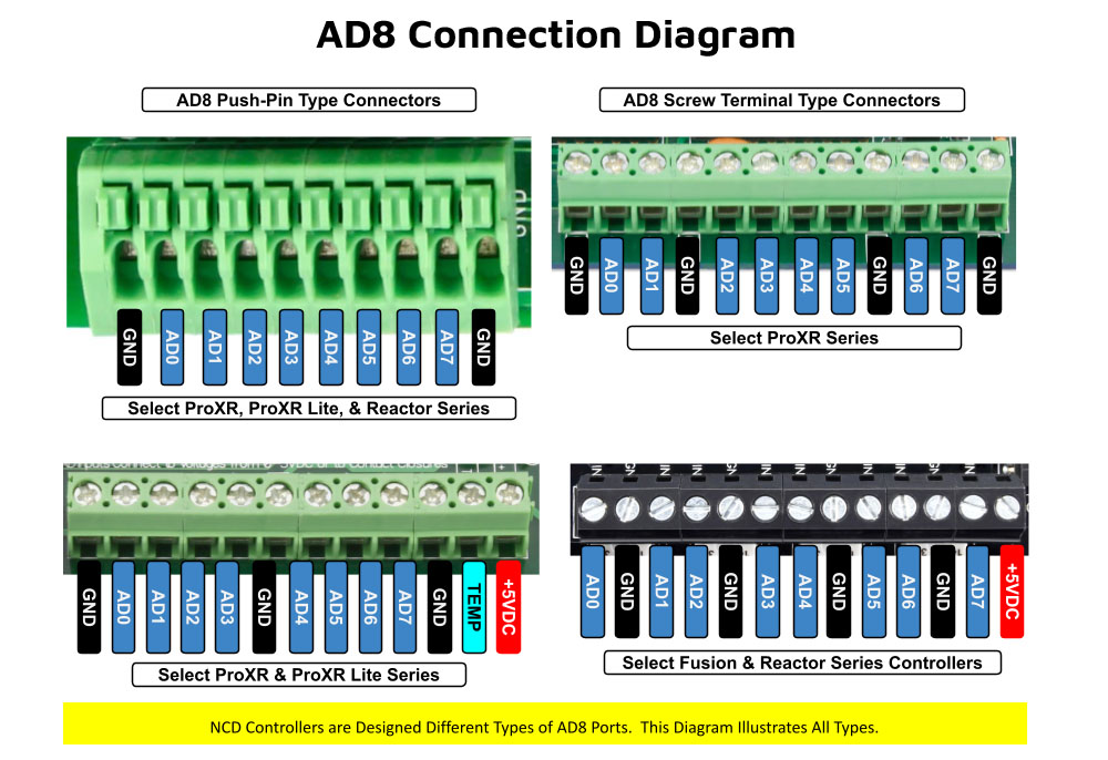
As shown in the graphic, ProXR AD8 controllers are available with multiple analog input connector options. One of the connector styles shown corresponds to the specific board you are viewing, allowing you to quickly identify how sensors will physically connect. All analog inputs share a common ground, simplifying wiring and making it easy to connect multiple sensors to a single controller.
Once connected, A/D input values can be used consistently across N-Button and Base Station software for automation, relay control, monitoring, and diagnostics. This unified approach ensures predictable behavior from hardware to software, whether you are building a simple monitoring system or a fully automated control solution.
Analog Inputs Controlling Relays
ProXR AD8 relay controllers allow analog inputs to directly control onboard relays using the same A/D input data used by N-Button and Base Station software (see Relay Activator section below). This makes it easy to monitor sensor values, automate relay behavior, and visualize input data across all supported software tools.Analog to Digital Connections
AD8 controllers are designed for stable sensor and switch monitoring. A/D inputs should never be left floating - each input must connect to a voltage or ground.A built-in 10K pull-up/pull-down resistor (jumper-selectable) ties each input to +5V or ground to prevent floating conditions. While this resistor adds slight loading, the improved stability far outweighs any minor interference.
AD8 Command Set
The AD8 Command Set reads analog voltages using the controller's 8-channel 8/10-bit ADC.- 8-bit mode: Converts 0 - 5V to values from 0 to 255
- 10-bit mode: Converts 0 - 5V to values from 0 to 1023
What a Command Looks Like
At its simplest, an AD8 command is only two bytes:254 150 - Read Input 1
0xFE 0x96 - If you require Hex
The controller processes the command and returns a value byte Decimal: 0-255, Hex: 0x00-0xFF when the operation completes. For the complete list of commands, download the AD Quick Start Guide.
View A/D Input Data in Real Time
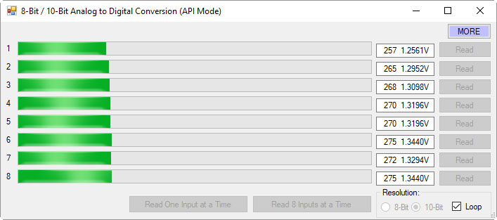 Base Station software allows you to read all analog inputs in real time while clearly displaying the exact command data being sent to and from the controller. In the example shown, all eight A/D input channels are read simultaneously and displayed as live numeric values along with a real-time graph, making it easy to visualize how each input changes over time.
Because Base Station shows the actual commands used to read the A/D inputs, it becomes an invaluable learning and diagnostic tool. You can see precisely how input values are requested, returned, and interpreted by the controller, then copy those commands directly into your own applications or custom software. This dramatically simplifies development, testing, and troubleshooting when integrating A/D inputs into larger systems.
Whether you are validating sensor behavior, monitoring multiple inputs at once, or building your own custom control software, Base Station gives you clear visibility into both the data and the communication behind it.
💡 Relay Pros ProTip:
Base Station can show you the exact command used to read the analog inputs. Click the More button in the upper-right corner of the Base Station window to expand the interface and display the command data being sent to and from the controller.
As you read inputs or monitor channels in real time, the software displays the precise commands used to request the A/D values and the data returned by the controller. This makes Base Station an excellent learning tool for developers - you can watch the commands being generated and then use the same decimal or hexadecimal values directly in your own software.
AD8 Relay Activator
Control relays with a switch or button connected directly to the board for manual control. For full details download the AD8 Relay Activator Quick Start Guide.
Relay Activator
Relay Activator and Analog Inputs
Base Station Software's Relay Activator is ideal for applications that primarily rely on computer control but still require occasional manual operation. By connecting external buttons or switches, you can take direct, hands-on control of any relay without giving up software-based control.This creates true bi-directional control. For example, a relay can be turned ON through the computer interface and later turned OFF using a physical switch - or vice versa. Whether you're testing, troubleshooting, or building a hybrid manual/software-controlled system, Relay Activator keeps everything synchronized and predictable.
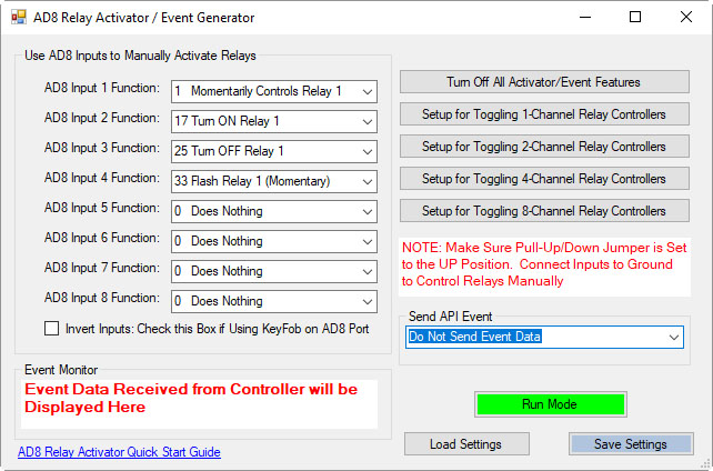 As shown in the example, each input includes a pull-down menu that allows you to select exactly how that input will control a relay. This makes configuration fast and intuitive - simply choose the desired action for each input without writing any code.
Each of the 8 input channels can be configured to control relays 1 through 8, with multiple action types available. This flexibility allows every input to perform exactly the function your application requires.
This level of control makes Relay Activator perfect for operator panels, test benches, safety overrides, and any application where manual interaction and software automation need to work together seamlessly.
AD8 Relay Activator Quick Start Guide.
Available Relay Actions per Input
Each input can be assigned one of the following actions:
- Momentary Control - Activates the relay only while the input is engaged
- Toggle Relay State - Alternates the relay between ON and OFF
- Turn Relay ON - Forces the relay into the ON state
- Turn Relay OFF - Forces the relay into the OFF state
- Flash Relay (Momentary) - Pulses the relay while the input is active
- Flash Relay (Toggle) - Toggles flashing behavior ON and OFF
💡 Relay Pros ProTip
Use the Turn Relay OFF action as a panic-stop or fail-safe control. A single button, switch, or sensor input can immediately force one relay - or multiple relays - into the OFF state. This is ideal for emergency stops on machinery, instantly disabling door locks, or overriding automation logic when a quick shutdown is required.AD8 with N-Button
Using N-Button software, you can control relays, build desktop meters that show real-time readings from the AD8 inputs. You can also create automatic push notifications messages triggered by those sensor values.
N-Button Software
Using A/D Inputs with N-Button
N-Button Lite and Pro support powerful A/D Input Automation rules that allow you to automatically control relays based on analog input levels. Simply define a voltage threshold or range, and N-Button will energize or de-energize relays as conditions change.N-Button also supports Send Email and Text Message actions (Push Notifications), enabling automatic alerts when an A/D input reaches a specific level or falls within a defined range. Relay control and notifications can work together seamlessly, all driven by live A/D input data.
Works Seamlessly with N-Button Software
- Build desktop meters that show real-time sensor data
- Create dashboards with multiple sensor feeds
- Trigger Push Notification alerts from A/D thresholds
- Control relays based on sensor conditions - no programming required
Using the Input Information
 N-Button allows you to use A/D input values in multiple ways without writing code. Numeric values or value ranges can be used to:
- Trigger text or email alerts when thresholds are exceeded
- Control individual relays or banks of relays
- Display live readings on customizable desktop meters
Control Relays with A/D Inputs
N-Button Lite/Pro software makes it incredibly easy to automate relay control using A/D input levels from this board. Simply create an Automation rule that links any A/D input channel to any relay channel. When the input voltage reaches the threshold you define, the relay energizes (turns on). When the input drops below that threshold, the relay de-energizes (turns off). No programming required.Precision + Performance
High-resolution readings ensure accurate measurements, even in demanding environments. Stream live data or automate actions based on your input thresholds.Create Desktop Meters
Each meter can be individually labeled, like the "Soil Moisture" label shown, making it easy to identify each sensor at a glance. Meter increments are fully customizable - the "Customizable Increments" callout shows how you can adjust the scale to match your application, whether you need fine-grained precision or a broader overview.
N-Button also allows you to arrange multiple meters on your desktop, creating a personalized dashboard that updates in real time. This makes it simple to compare different sensors side by side, spot trends, and react quickly if readings go outside expected ranges (unless you have the relays set automatically). Whether you're monitoring a single sensor or a full set of eight, N-Button makes live data monitoring intuitive and actionable.
Push Notification
N-Button software also includes a powerful point-and-click messaging system that sends alerts to the recipients you choose. Because N-Button runs on your PC, it can automatically deliver text messages and/or emails directly from your computer.Send SMS and email alerts when voltage levels are reached. Customize the subject and message to identify exactly what triggered the alert. You can even set repeat notifications at a defined interval until the input level returns to normal.
Visit our N-Button Page
Base Station Taralist Setup
"Run relays automatically based on your schedule"
Taralist Setup Overview
Taralist controllers are powerful, flexible, and incredibly reliable once your schedule is loaded - but setting them up is not a plug-and-play process. If you're comfortable with basic PC software, COM ports, and following on-screen prompts, you'll be fine. If not, this may not be the right product for you.This page gives you a big-picture look at what's involved so you know what to expect before you purchase.
1. Setup Requires a Windows PC + Base Station Software
All Taralist controllers must be configured using NCD's free Base Station Software.You'll create your schedule on your computer, upload it to the board, and the board runs that schedule on its own after that.
No coding is required, but you will be interacting with a configuration tool.
2. You'll Need to Establish a Connection (USB, Ethernet, or WiFi)
To configure a Taralist controller, you must connect it to your PC through one of the supported communication methods:- USB
- Board appears as a virtual COM port
- Easiest, most reliable setup path
- Required for recovering misconfigured controllers
- Ethernet
- The board connects to your router or network switch
- Base Station communicates over the network
- You'll need the board's IP address
- Static IP is ideal, but DHCP works fine for setup
- WiFi
- Requires joining the board to your WiFi network first
- Can be trickier than USB or Ethernet
- Once connected, Base Station communicates wirelessly
- Taralist WiFi models can also use daily NTP time sync
- Open Base Station
- Select the correct COM port or network device
- Load the board's current configuration
- Begin building your schedule
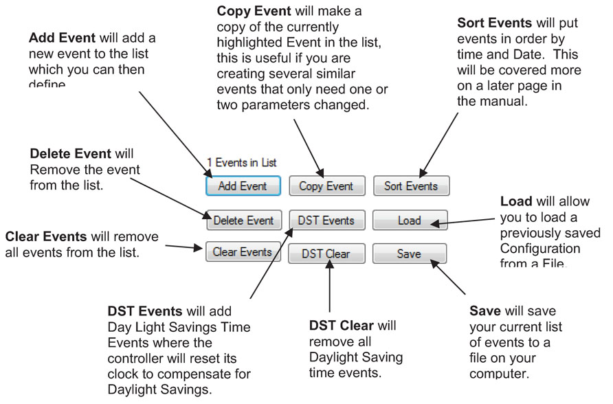
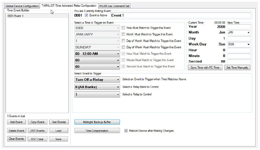
3. Creating Your Schedule (Up to 1000 Events)
Inside Base Station, you'll build your event list.Each event can specify:
- Exact time (year, month, date, day of week, hour, minute, second)
- Which relay(s) to turn on or off
- Priority (events at the bottom of the list override events above)
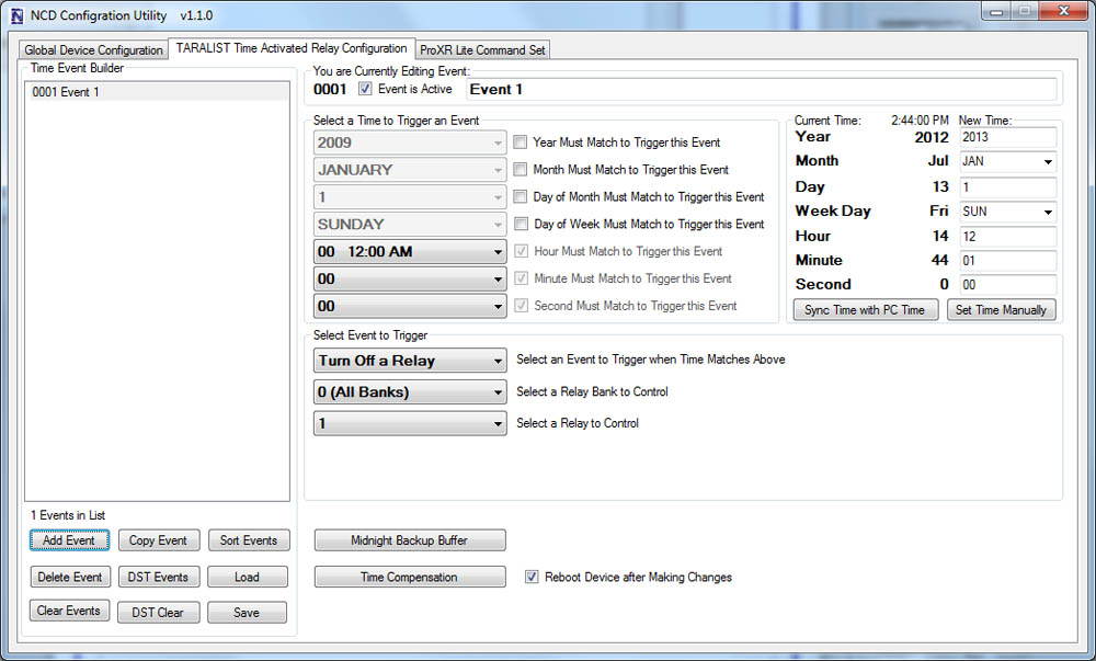
4. Setting the Clock
Before uploading your schedule, you'll set the Taralist's internal clock:- Sync to your PC's system time (most common), or
- Manually enter the date and time
5. Midnight Backup Buffer (VERY Important)
Every night at midnight, the controller stores all relay states.This prevents your logic from falling apart after a power outage.
You don't have to configure this feature, but you should understand that it exists - it's core to how Taralist keeps long-term schedules stable.
6. Uploading Your Schedule
Once your schedule is ready:- Switch the jumper to PROGRAM mode
- Upload your schedule to the board
- Switch back to RUN mode
- The board now runs autonomously
Keep Your Master File Handy. "Save your .tlt schedule files somewhere predictable." If you ever swap controllers, clone a schedule, or just need to adjust next season's timing, you'll thank yourself. The Taralist uses the same format across the line - so one file can travel.
Optional: Manually Control Relays from Your PC
 Base Station also lets you:
- Test relay states
- Override relays
- See which system (PC or Taralist logic) currently "owns" each relay
- Return control to Taralist logic afterward
Who Is This For?
We recommend Taralist controllers for users who are:- ✔ Comfortable on Windows
- ✔ Okay with basic COM port configuration
- ✔ Willing to follow a guided setup process
- ✔ Need recurring automation without software running 24/7
Understanding Clock Drift
All real-time clocks drift a little over time - even high-quality ones. Taralist controllers are typically very stable, but the onboard clock can naturally drift up to about 1 second per day.Temperature can also have a small influence:
- Cold environments: the clock may run slightly slower
- Warm environments: the clock may run slightly faster
Taralist includes a Time Compensation feature that lets you counteract drift so your schedule stays accurate long-term.
💡 Relay Pros ProTip:
Keep Your Timing Tight!
If ultra-precise timing matters (school bells, synchronized lighting, access events, etc.), here's the trick:
Use the Time Compensation tool to fine-tune drift.
It takes just a moment, and once dialed in, your Taralist can stay extremely accurate over long stretches.
For WiFi Taralist models, you get an even easier option:
Daily Automatic Time Sync
Your controller fetches the correct time from the internet once a day - meaning drift basically disappears.
Bottom Line
Taralist controllers are incredibly reliable, deeply configurable, and ideal for long-term autonomous scheduling - but setup is hands-on, technical, and requires a PC.If you're comfortable with that, you'll love what Taralist can do.
If not, no hard feelings - but this isn't the product you want.
Base Station Configuration
Reactor boards are configured using the Free Base Station Software. The GUI interface makes it easy to configure simple automation tasks with a point and click interface! Download Base Station
Base Station Reactor Configuration
Base Station Software
Base Station will assist you in learning how this device functions and is the ultimate reference tool for configuring, testing and controlling this device. Base Station software supports every feature of this device - no other controller manufacturer even comes close to offering this type of software. Base Station works by communicating with your controller to identify the model and provides the appropriate graphical user interface for setting up and testing the identified device. All Reactor configurations will be made through Base Station and an overview will be discussed below. To help you get started and learn this controller Quick Start Guides are available for just about every feature. As you discover a feature in Base Station a link is provided where you can easily download the Quick Start Guide. Download Base StationeConfigure Each Input
The Reactor Relay allows users to define the activation of a relay or an event based on the voltage readings of the analog inputs. An input can trigger a relay directly or an input can trigger an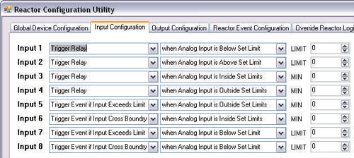 event, such as a timer. If an input triggers a relay, the relay may turn on. If an input triggers a timer event, a timer may be started,
but a relay may or may not be turned on based on how you have configured the controller (the time delay may be before the relay triggers). Triggering an event does not mean you are triggering a relay, it just means you are triggering an internal function. Relays may be associated
with this internal function to achieve a large number of possible operations.
event, such as a timer. If an input triggers a relay, the relay may turn on. If an input triggers a timer event, a timer may be started,
but a relay may or may not be turned on based on how you have configured the controller (the time delay may be before the relay triggers). Triggering an event does not mean you are triggering a relay, it just means you are triggering an internal function. Relays may be associated
with this internal function to achieve a large number of possible operations.
Using Input Values

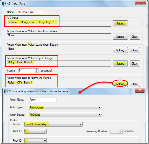
Reading from Left to right, the settings above indicate Input 1 will trigger a relay when Analog Input 1 is above 200. We have defined that a relay will turn on when the input level is defined by a value of 200.

In the above example, a relay is triggered when an analog input is inside a set range between 100 and 202. By defining two limits, you can further narrow the parameters for the activation of a relay. The limits can also be assigned to set the relay to be activated outside two set limits.
Output Configuration
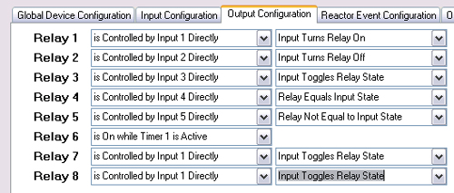 The configuration software makes it easy to configure each relay. Relays or multiple relays can be can be assigned to each input.
There are many ways to directly control a relay from an input. Relays 1-5 in the below example shows how inputs can turn relays on, off, toggle relay state, set the relay to match the state of the input, or set the relay to NOT equal the state of a input.
In the example below, Relay 6 is controlled by Timer 1. In other words, if Timer 1 is active, the relay will stay ON. Otherwise, the relay will turn off. This is a great way to activate a light for a given period of time. If you are interested in Time Delay Relay, timers will be discussed on our Time Delay Relay Page.
Complex Automation through Experimentation
Don’t be afraid to experiment with Reactor! Some complex automation can be achieved by experimenting with Reactor settings. Of course Reactor is capable of triggering relays and it can also trigger events. Relays can be associated with events, allowing you to play with all kinds of complex timing and counting settings. Events greatly expand the pallet of functionality available to Reactor.Computer Controlled Relays
Software developers who need remote access to a Reactor controller will find themselves at home.  The Reactor supports a very powerful computer-based command set, so it is possible for a computer to operate the relays and read sensor inputs.  The computer can over-ride the Reactor decision logic, trigger events, and return control of the relays back to the Reactor Logic. Configuration settings are stored in files that can be loaded into other Reactor controllers.Many More Options
We have just touched on the many ways the Reactor board can be configured. The applications that this board can be use in are extensive. For a more detailed look at the configuration and setup you can look at the Reactor Series Quick Start Guide.Reactor Video
Instant Control & Diagnostics
Free Base Station software gives you full, hands-on control of your controller the moment you plug it in. It automatically identifies your board, loads the correct interface, and lets you test, control, and verify every supported feature - making setup, learning, and troubleshooting fast and frustration-free.
Base Station Software
"Every feature, every device - no other board has this kind of software"
Compatible with All Boards on this Site
Base Station is a free software download that works by talking directly to your controller to identify the model, then automatically loads the correct graphical interface for controlling and testing that device. It's a great way to learn how any NCD controller works and doubles as a powerful diagnostic tool to verify your device is operating as designed.Base Station exercises every supported feature on every supported device. For learning, testing, and troubleshooting NCD boards, this is the ultimate reference tool.
Useful Features
There are some useful features to look for when using Base Station Software to control, test, or configure your device:- Links to Quick Start Guides and documentation
- Discovery of network devices with IP address display
- Command Set Window for viewing raw commands (especially helpful for ProXR users)
- Base Station displays commands in decimal or hexadecimal formats.
- Relay Activator with Analog Inputs

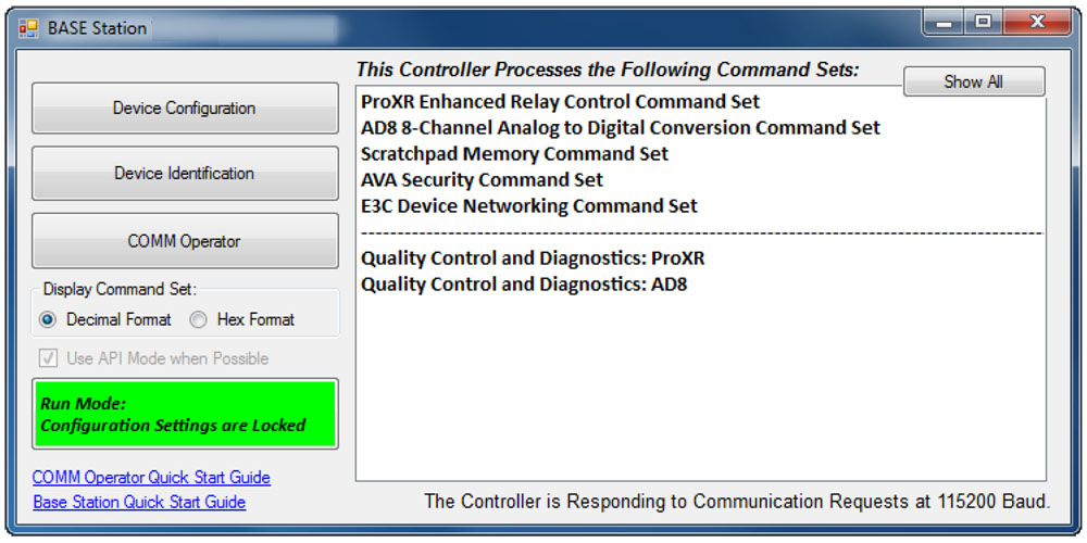
Device Identification
Click the Device Identification window to view important read-only info about your controller.Watch for the field labeled "Documentation Related to this Controller" - it's a complete list of articles connected to your device. Click any entry to open it. (Internet required.)
All devices released in 2012 and later support Device Identification.
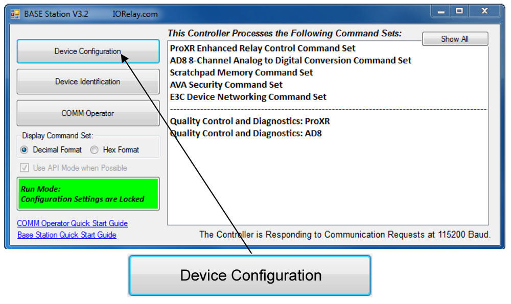
Device Command Sets
 Base Station asks the controller which command sets it supports, then displays them when the software launches. Some devices show more command sets, others fewer - it's always based on the board.
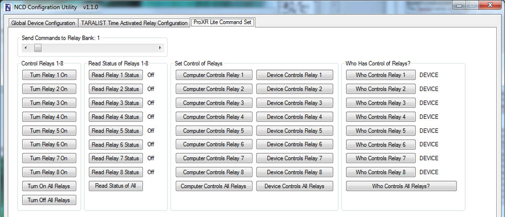
ProXR users can access the entire ProXR Command Set to turn relays on/off and run every available function.
Control All ProXR Functions
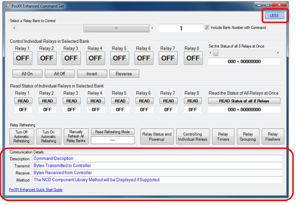
Turn relays on or off, read relay status, monitor inputs - Base Station gives full ProXR control through a clean point-and-click interface.For programmers, Base Station also shows every command being sent to the board, making it a great tool for learning and development.
💡 Relay Pros Pro Tip:
Use Base Station as a Command Generator! Base Station is not only a control interface - it is also a powerful development tool. Click the More button in the upper-right corner of the window to expand the interface and display the command output being sent to the controller. As you operate relays using the point-and-click controls - including toggle commands, timers, and flashers - the software displays the exact command being transmitted.
Developers can use this feature to quickly determine the decimal or hexadecimal commands required for heir own software without manually building commands from the documentation.
AD8 Relay Activator
Control relays with a switch or button connected directly to the board for manual control. For full details download the AD8 Relay Activator Quick Start Guide.
Relay Activator
Relay Activator and Analog Inputs
Base Station Software's Relay Activator is ideal for applications that primarily rely on computer control but still require occasional manual operation. By connecting external buttons or switches, you can take direct, hands-on control of any relay without giving up software-based control.This creates true bi-directional control. For example, a relay can be turned ON through the computer interface and later turned OFF using a physical switch - or vice versa. Whether you're testing, troubleshooting, or building a hybrid manual/software-controlled system, Relay Activator keeps everything synchronized and predictable.
As shown in the example, each input includes a pull-down menu that allows you to select exactly how that input will control a relay. This makes configuration fast and intuitive - simply choose the desired action for each input without writing any code.
Each of the 8 input channels can be configured to control relays 1 through 8, with multiple action types available. This flexibility allows every input to perform exactly the function your application requires.
Available Relay Actions per Input
Each input can be assigned one of the following actions:
- Momentary Control - Activates the relay only while the input is engaged
- Toggle Relay State - Alternates the relay between ON and OFF
- Turn Relay ON - Forces the relay into the ON state
- Turn Relay OFF - Forces the relay into the OFF state
- Flash Relay (Momentary) - Pulses the relay while the input is active
- Flash Relay (Toggle) - Toggles flashing behavior ON and OFF
AD8 Relay Activator Quick Start Guide.
Reactor Users
Reactor Events Settings
All Reactor configuration is handled inside Base Station.You can define when a relay or event activates based on the voltage readings of analog inputs. Inputs can trigger relays directly or trigger timed events.
The Reactor GUI only appears when Base Station detects a Reactor board, and some functions may not display for other board types.
TaraList Users
TaraList Setup
Base Station includes configuration tools and scheduling upload controls for TaraList Time Activated Boards.TaraList users will see setup pages for creating and uploading time schedules. ProXR users won't - those pages appear only when Base Station detects a TaraList controller.

Device Configuration
 All devices are configured prior to shipping. The Configuration page is for experienced users who wish to customize their device. Most users have no need to customize their device differently from what is configured prior to shipping.
 Supported Devices
Not all devices support Device Configuration. All Devices released in 2012 and later support Device Configuration. Some configuration settings will affect device communication timing, which can render a device too fast for the chosen interface. If you ever lose communications with your controller, power down the controller, set the Program/Run jumper to the Program Position and power up the device. Attempt Communication at 57.6K or 115.2K Baud. If problems persist, install a ZUSB communications module to recover device settings.Configuration and Run Modes
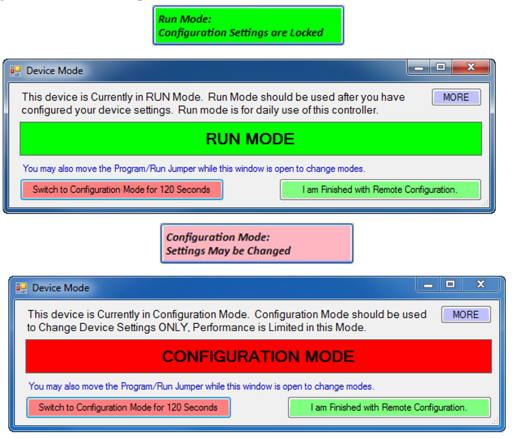
All NCD controllers have two modes of operation: Configuration mode and Run mode. Normally, the controller should always be in RUN mode. Use Configuration mode if you want to make changes to the settings of the controller. Configuration mode is a temporary mode. Configuration mode allows you to write parameters to the controllers for changing device settings. Run mode does not allow accidental changes to configuration parameters. On-board memory is protected from write operations in Run mode.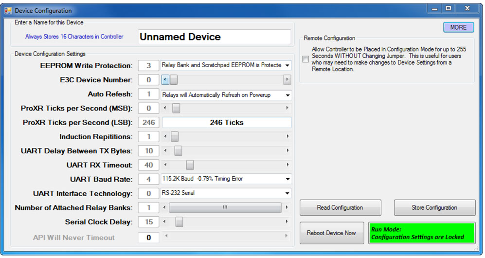 Traditionally, you needed to move a jumper to change device modes. You can still do this, but 2012 and later controllers allow you to put the device in Configuration mode for a short period of time without moving the jumper. This is very convenient when you need to setup the device in a remote location.
So far, the concept of Configuration and Run mode is pretty simple. But there are special rules about the use of these modes that must be followed to prevent loss of communications. Most notably, changing the baud rate or any of the UART settings can cause a loss of communications. This is where the hardware Configuration/Run jumper comes into play. When the jumper is set to Configuration mode and the controller is powered up, the controller will always load safe communication settings so you can recover communications with the device.
Software Configuration Mode
Software Configuration Mode allows you to send a command to put the controller in Configuration mode for up to 255 seconds. This is extremely useful if you need to make changes to the controller from a remote location. If you change the baud rate settings, our Base software will attempt to Re-Sync to the device. This is effective most of the time, but occasionally, you may need to exit and re-run Base software.If you make changes to any parameters while in software configuration mode, the controller will not respond to these changes until the Reboot command is issued. Our software automatically issues the Reboot command at the appropriate times, allowing you to make changes without ever touching the device. However, configuration settings can lead to a loss of communications, so if you intend to make changes to communication parameters, make sure the Configuration/Run jumper is accessible in case you need to boot up the controller in “Safe” mode of 57.6K or 115.2K Baud.