
Relay Logic
RELAY_LOGIC

Relay Wiring Made Simple
From simple on/off switching to advanced AND/OR logic, these examples show exactly how to connect your relays for real-world applications. Learn the tricks to control lights, motors, sensors, and more with confidence.
Get a printout of this page
Relay Logic
"Using a light as an example load, let's wire to the board"
Relay Wiring Samples
This page provides simple examples showing how to wire a single relay - or multiple relays - for common switching applications. We use a light as the example load, but you can substitute a gate controller, security panel input, dry contact device, motor trigger, or most other switched loads. These wiring samples demonstrate different ways to connect relays to achieve the switching behavior you need.Relay Types
SPDT Relay
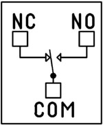 SPDT (Single Pole Double Throw) relays include three terminals: Common (COM), Normally Open (NO), and Normally Closed (NC).
- When the relay is off, COM is connected to NC.
- When the relay is energized, COM switches to NO.
Your load can be wired to either the NO or NC terminal depending on whether you want the device to turn on when the relay activates or when it releases. Examples below demonstrate both wiring methods. The SPDT relays offered on this site are 5-Amp, 10-Amp and 20-Amp models.
SPST Relay
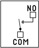
SPST (Single Pole Single Throw) relays provide two terminals: Common (COM) and Normally Open (NO).
When the relay coil is energized, COM connects to NO to power the load. The only SPST relays offered on this site are our 30-Amp models. All SPDT examples shown on this page apply to these relays as long as the example does not require a Normally Closed terminal.
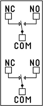
DPDT Relay
A DPDT (Double Pole Double Throw) relay contains two SPDT switches that operate together.
- Each side includes its own COM, NO, and NC terminals.
- Both internal switches change state at the same time.
This allows you to control two independent circuits with one relay. Wiring for each side of a DPDT relay follows the same rules as an SPDT relay, so the examples on this page apply directly. We offer the DPDT relays in 1-Amp, 3-Amp and 5-Amp models on ProXR boards starting at 8 relays.
Relay Grouping
Relay Grouping in the ProXR Command Set lets you combine individual relays to function like a DPDT relay using separate channels. This is ideal when you need to control multiple relays simultaneously or exceed the 5-Amp switching limit of our standard DPDT relays.Relay Logic Examples
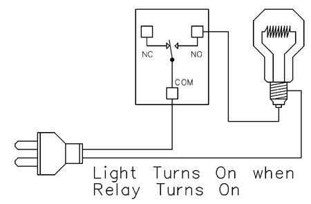
Example 1 - Simple Off/On Control
This example shows the most basic way to use a relay to switch a device such as a light. When the relay energizes, its NO (Normally Open) contact closes to COM (Common), completing the circuit and turning the light on.Only a single power wire is switched in this setup, making it the simplest method for controlling a light - or any device - using a relay.
Use this example for switching a light or any device you want to power only when the relay is on.
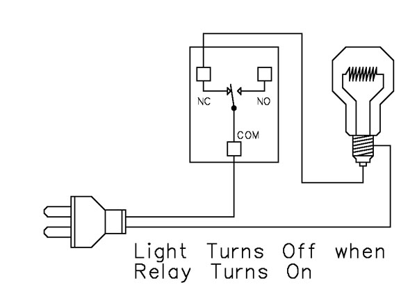
Example 2 - Simple On/Off (Using NC Contact)
This wiring method keeps the light on by default. The relay switches a single power wire through the COM (Common) and NC (Normally Closed) terminals.When the relay is not energized, the NC contact is closed to COM and the light remains on.
When the relay energizes, the NC contact opens, interrupting power and turning the light off.
This approach is ideal for devices that stay on most of the time, reducing relay wear since it doesn't need to remain energized to keep the device powered. It's also a useful method for power-cycling equipment - energizing the relay momentarily will turn the device off.
💡 Relay Pros ProTip:
For devices that stay on most of the time, use the NC contact. This reduces relay wear and extends the life of both the relay and your power supply.
Example 3 - AND Logic Using Two Relays
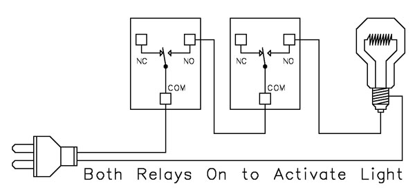 This example shows how two relays can work together so a light turns on only when both relays are energized. This creates an AND Logic condition:
Relay 1 AND Relay 2 must be on for the light to receive power.
A single power wire is switched, but it must pass through both relay contacts before reaching the light. This setup is ideal when two conditions must be met at the same time - such as requiring input from multiple sensors or system parameters.
MirC/MirX/MirM Users:
This wiring requires two contact closure inputs on the sender board before the receiver's relay activates. Use this approach when two independent outputs must close before turning on the light.For example, a light could turn on only when:
1. A light sensor detects it's dark AND
2. A motion sensor detects activity in the room
Example 4 - AND Logic Using Three Relays
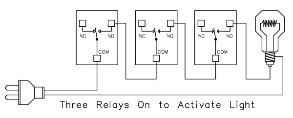 This example expands on the previous AND Logic concept. Here, the light will turn on only when all three relays are energized:
Relay 1 AND Relay 2 AND Relay 3 must be on for power to reach the light.
A single power wire is routed through all three relay contacts. Wiring from the NO (Normally Open) of Relay 1 to the COM (Common) of Relay 2, then from the NO of Relay 2 to the COM of Relay 3, creates a series path that requires every relay to energize before the light can activate.
This method can be scaled easily - just continue wiring NO of each relay to the COM of the next relay. Add as many relays as needed to meet your logic or safety requirements.
Example 5 - AND/OR Logic with Override
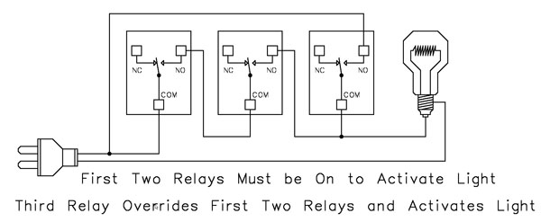 This example demonstrates a combined AND/OR logic setup. The light will turn on when:
- Relay 1 AND Relay 2 are both energized OR Relay 3 is energized (override)
- For example:
- Relay 1 = night/day sensor
- Relay 2 = motion sensor
- Relay 3 = manual override (local switch)
A/D Board Users:
The Relay Activator function on any A/D board or ProXR Lite board lets you connect a button or switch to any A/D input. This input can then control the override relay, giving you a convenient local button to manually override the first two relays.MirC/MirX/MirM Users:
Add a manual button or switch to trigger the third relay when you need direct control instead of sensor-driven control.Reactor Users:
A local button or switch can be wired to the third relay input to provide a manual override for sensor-based logic.Example 6 - OR Logic (Either Relay Activates)
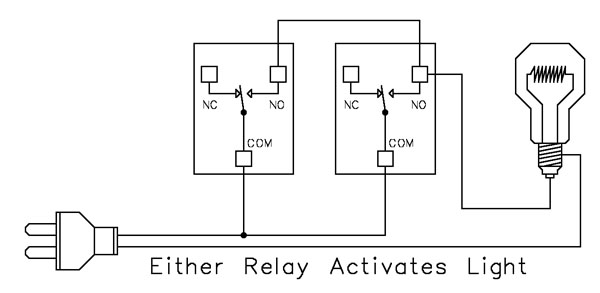 This example demonstrates OR Logic - the light will turn on when either relay is energized. Only one power wire is switched, but it can pass through Relay 1 or Relay 2 to reach the light.
- If Relay 1 activates, the light turns on
- If Relay 2 activates, the light turns on
- If both activate, the light remains on
- A timer controlling one relay, with a manual or secondary control for the other.
- Two sensors where either condition (motion detected or low light, for example) should activate the light.
A/D Board Users:
The Relay Activator function on any A/D board or ProXR Lite board lets you connect a button or switch to any A/D input. This input can then be used as a manual control of the relay.MirC/MirX/MirM Users:
Add a manual button or switch to trigger the third relay when you need direct control instead of sensor-driven control.MirC/MirX Users:
Wire two contact closure inputs into the sender board - either input can trigger the receiver relay to control the light.Example 7 - 3-Way Switch (Relay-Based 3-Way Control)
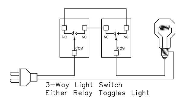 This example shows how to create a 3-way light switch setup using relays. A traditional 3-way circuit allows two switches to control the same light from different locations. In this wiring sample, each physical switch is replaced by a relay - but the operation is the same.
Only one power wire is switched, and the relays toggle the light depending on their current state.
- Activating either relay will toggle the light
- Activating both relays at the same time has the same effect as flipping both switches at once
Example 8 - DC Motor Direction Control
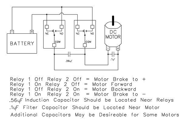 This example demonstrates how to control the direction of a DC motor using two relays. By changing how the motor's leads connect to power, you can run the motor forward, reverse, or place it in a brake state. Braking is achieved by tying both motor terminals to the same power connection, which stops rotation through Faraday's Law.
- Relay Operation Summary
- Relay 1 Off / Relay 2 Off → Motor Brake to +
- Relay 1 On / Relay 2 Off → Motor Forward
- Relay 1 Off / Relay 2 On → Motor Reverse
- Relay 1 On / Relay 2 On → Motor Brake to -
- The induction suppression capacitor prevents the relay from shutting off due to motor back-EMF
- The 0.1µF filter capacitor reduces electrical noise, especially useful when powering sensitive electronics such as radios or amplifiers.
- Capacitor Placement
- Place the induction suppression capacitor near the relays
- Place the filter capacitor near the motor
- Additional capacitors may be needed for certain motors
Motors draw significantly more current at startup than during continuous operation - often 2-3 times their rated running current. For example, a motor rated at 5A (125VAC) may require 10-15A to begin turning. Always select a relay that exceeds the motor's initial inrush current, not just its running current. In this case, a 20-30A relay provides optimal performance and longevity.
💡 Relay Pros ProTip:
Motors and inductive loads often draw 2-3x their rated current at startup. Always choose a relay that exceeds the motor's inrush current, not just its running current.