TLR120_WIFI Time Activated Relay
Time Relay 1-Channel 20-Amp with Wi-Fi Interface

Use your computer to setup the time schedule and store your schedule into the TLR120_WIFI controller. Once stored, the TLR120_WIFI does not require a computer, and will activate relays according to a schedule that can be as simple or as complex as your application requires.
Time Activated with Wi-Fi Interface
The TLR120_WIFI is equipped with firmware built into the board that will allow a time schedule to trigger relays. The TLR120_WIFI know what time and day it is and will trigger relays according to your time schedule. Up to 1000 events can be in the schedule!
TLR120_WIFI The Ideal Choice
The TLR120_WIFI Taralist Relay uses a Wi-Fi interface that can be accessed within your Wi-Fi network. Once configured the computer is no longer needed and the board will operate on it's own! Access to the board from anywhere on the network or internet to make configuration changes or override current settings! The computer is needed to set your time schedule and upload it to the board. Making this the ideal choice for controlling relays using a time schedule!
Up To 1000 Events
The TLR120_WIFI can store up to one thousand events! If your current time schedule software only allows you a limited amount of settings for things like school bells and shift changes there is more than enough with this controller!
Time Controlled Relay
The TLR120_WIFI includes a Wi-Fi interface for easy
configuration and controlling the relays through youyr Wi-Fi network.
Extremely Powerful, Very Reliable Time Activated Relay!
Resources:
Here's Where to Order:
800-960-4287
417-646-5662
Wi-Fi Time Schedule Control
Wireless Upload of Time Schedule
Upload and Manual Control of Relays From Anywhere on the Network
Trigger Relays with a Time Schedule


 Connect your controller directly to your network using standard TCP/IP communication. Configure DHCP or static IP settings, port numbers, and serial baud rates using the integrated web interface while in Soft AP mode.

 Whether you're using:
 The Taralist series have an integrated battery backed Real Time Clock with memory that allows users to control relays based on a time schedule. Use your computer to setup the time schedule and store your schedule into the board. Once stored, the Taralist does not require a computer, and will control the relay according to a schedule that can be as simple or as complex as your application requires.
 Override functions are also supported. So if the normal schedule activates a light during weekdays, but you don't want the light to come on during holidays, simply program your holiday schedule to prevent the light from activating according to your normal schedule.

 TaraList boards have some amazing abilities when it comes to making decisions on their own based on the events you configure, but you can take control of the relays at any time from a computer as long as communications are established between your computer and the Time Relay device.


 XR Expansion Boards are designed for long life just as the ProXR boards, you should expect to get years of service from expansion board and literally 2-million cycles from the relays on board. With a 5-year warranty and a money back guarantee add more relay anytime the need arises!
  The PWR12 is regulated power supply providing clean power necessary for
the performance of these boards. The PWR12 US power supply is a 120VAC to 12VDC 1.25A 60Hz regulated
power supply and it plugs into the barrel connector on the board. The output connector is a 2.1mm I.D. x 5.5mm
O.D. x 9.5mm R/A barrel connector.
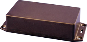
 The GFL Enclosure is an undrilled, non-waterproof enclosure and is available at checkout for this controller.
 Wiring is done directly to the Relay terminals using a common 1/4" quick disconnect terminal. These quick-disconnect
insulated spade wire terminals offer the fastest way to connect and disconnect wires to the relay. Easy to Apply:
Crimp with pliers after inserting the wire, no soldering required, making electrical maintenance and wiring work easier
and more efficient.
 Controlling
an inductive load using our relay controllers requires the use of induction suppression capacitors. The purpose of this capacitor
is to absorb the high voltages generated by inductive loads, blocking them from the contacts of the relay. Without this capacitor,
the lifespan of the relay will be greatly reduced. Induction can be so severe that it electrically interferes with the microprocessor
logic of our controllers, causing relay banks to shut themselves down unexpectedly.
 Taralist
boards are configured using the Free Base Station Software. The GUI interface makes it easy to
configure time schedules with a point and click interface! Base Station can also be used to take
manual control of the relays to override the time schedules.
 SPDT (Single Pole Double Throw) relays include three terminals: Common (COM), Normally Open (NO), and Normally Closed (NC).


 This example shows how two relays can work together so a light turns on only when both relays are energized. This creates an AND Logic condition:
 This example expands on the previous AND Logic concept. Here, the light will turn on only when all three relays are energized:
 This example demonstrates a combined AND/OR logic setup. The light will turn on when:
 This example demonstrates OR Logic - the light will turn on when either relay is energized. Only one power wire is switched, but it can pass through Relay 1 or Relay 2 to reach the light.
 This example shows how to create a 3-way light switch setup using relays. A traditional 3-way circuit allows two switches to control the same light from different locations. In this wiring sample, each physical switch is replaced by a relay - but the operation is the same.
 This example demonstrates how to control the direction of a DC motor using two relays. By changing how the motor's leads connect to power, you can run the motor forward, reverse, or place it in a brake state. Braking is achieved by tying both motor terminals to the same power connection, which stops rotation through Faraday's Law.


