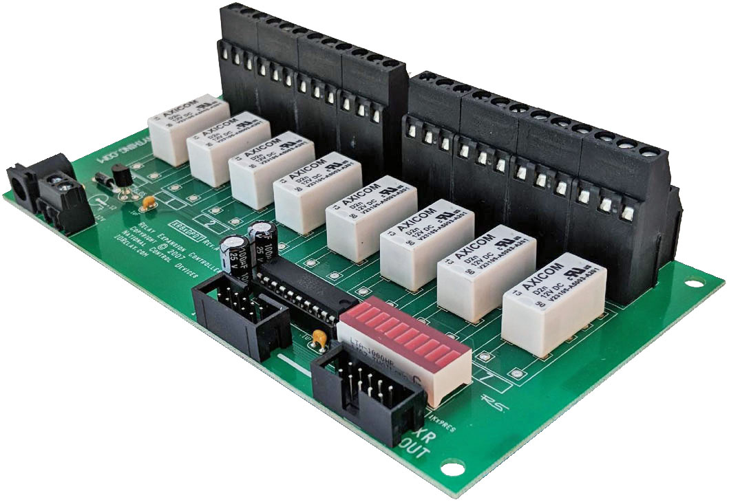
Expansion Board 32-Channel 10-Amp
XR3210
XR Expansion Board
Add 32 relays to your system in seconds. The XR3210 XR Expansion Board connects directly to any ProXR or Taralist controller equipped with an XR Expansion Port, instantly adding 10-Amp relays without changing your command structure.This expansion board includes the required XR expansion cable for quick setup. Simply plug the board into the XR Expansion Port and your new relays are ready to use.
Powered by 12VDC, the board supports both screw terminal wiring and a 2.1mm center-positive barrel connector for flexible installation.
Mix and match expansion boards to build the exact system your application requires. Add additional relay banks at any time, up to a maximum of 256 total relays.

32-Channel ProXR Expansion Board
- 32 10-Amp Relays Installed
- Single Pole Double Throw (SPDT) Relays
- Wire to Normaly Open or Normaly Closed Position - 12 Guage Solid Core Wire Capacity
- Temperature Rating -40° C to 85° C
- Expandable to 256 Relays - Compatible Controllers
- All ProXR Controllers
- All Taralist Time-Activated Controllers
- Not compatible with ProXR Lite boards
- Does not operate independently - Onboard XR Expansion Ports
- Connects to ProXR or other expansion boards
- Daisy-chain multiple expansion boards
- Control up to 256 total relays
- Includes 6" ribbon cable
)
ProXR Expansion Board
Expansion Boards plug into the XR Expansion Port on any ProXR, Taralist or Potentiometer Board to add more relays. Expansion boards can be daisy chained together to add up to 256 relays as needed.
The XR Expansion Port
"Running out of relays? Just plug in more!"
Add Relays as Your Needs Grow
ProXR Controllers were built with relay expansion in mind. The XR Expansion Port lets you add banks of external relays to any ProXR or Taralist board equipped with an XR Expansion port. Expansion boards can be added at any time as your system grows, up to a maximum of 256 total relays.As expansion boards are added, additional relay banks become available automatically. Simply add another expansion board whenever you need more relays.
Relay Banks - How Large Systems Stay Simple
Each bank contains:
- Relay 1 through Relay 8
For example:
- An 8-relay controller uses one bank
- A 32-relay controller uses four banks
- A 64-relay setup uses eight banks
- Select a bank
- Send simple relay commands within that bank
Linking XR Expansion Boards Together
XR Expansion Boards include both an XR Input and XR Output connector. Connect the XR Output on your ProXR controller to the XR Input on the first expansion board. To add more relays, connect the XR Output of one expansion board to the XR Input of the next board in the chain.You can mix and match different relay types on expansion boards to match your application. A 6" expansion cable is included with each expansion board.
For best reliability, keep all expansion cabling as short as possible. Maximum expansion length and total relay count depend on your installation, electrical noise, and overall cable length. For best compatibility, the combined length of the controller, expansion boards, and cables should not exceed 1-2 meters.
Mix & Match
Expansion boards do not need to match the relay type or amperage of the main controller or other expansion boards. Mix and match expansion boards to get the exact relay types and current ratings your application requires.💡 Relay Pros Pro Tip:
You can mix and match relay types and amperages to dial in exactly what your application requires - for example, adding a bank of DPDT relays when all the other boards have SPDT relays. This gives you ultimate flexibility as your system grows.
Will Not Operate Independently
This Expansion Board gets it's commands from the main ProXR, Taralist or Potentiometer board and will not operate independently. This board MUST be plugged into a ProXR or Taralist board to operate and will not function on it's own.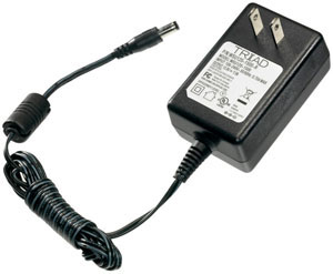
Essential Power Requirements
All XR expansion boards require their own 12 VDC power source. A regulated 12 VDC supply must be connected directly to each expansion board for proper operation.We offer a compatible wall-plug power supply at checkout, or you may use your own regulated 12 VDC supply. Learn More
Maximum Relay Rating Notes
ProXR is capable of expanding to an absolute maximum of 256 Relays. In some cases, it may not be possible to control all 256 relays, particularly in applications where high noise levels may be involved. Experimentation may be required, as it is not possible for us to guarantee all users will be able to utilize all 256 relays in every application. Noise tends to accumulate when several expansions are connected together. For best results, the XR expansion cables must be as short as possible.
RoHS Compliant
Expansion boards are led free and RoHS Compliant. If your requirements are for RoHS compliant parts every expansion board is manufactured with RoHS compliant led free parts and solder.2-Million Cycles
 XR Expansion Boards are designed for long life just as the ProXR boards, you should expect to get years of service from expansion board and literally 2-million cycles from the relays on board. With a 5-year warranty and a money back guarantee add more relays anytime the need arises!
 Relay Expansion Videos
Plan Your Power with Confidence
Get reliable performance every time! Use these real-world specs to build accurate power budgets, protect your board, and ensure every relay and module runs smoothly under any conditions.
Power & More
"Reliable Power = Reliable Switching"
Board Performance Ratings
This tab brings together the essential performance ratings you'll want to know for NCD SPDT Relay Controllers and their supported communication modules. You'll find practical electrical requirements, power consumption estimates, operating limits, relay timing details, and more-all based on typical 12VDC operation at 70°F (21°C). Think of it as a reliable snapshot of how our hardware behaves under real-world conditions. Because every installation is unique, some values are estimates and may evolve as designs and testing continue. Use this information as a planning tool to help you choose the right controller, build an accurate power budget, and understand the capabilities built into every NCD SPDT relay board.Powering from a Battery or Solar Panel?
NCD relay controllers are well-suited for battery-powered and solar-charged applications when operated within the recommended 10 - 15VDC range. This makes them ideal for remote, mobile, and off-grid installations using common 12V battery systems with solar charging. The power consumption data on this page helps you estimate runtime, size your battery, and avoid over-discharge. Staying within the voltage limits ensures stable, reliable operation in long-term battery and solar-powered setups.💡 Relay ProTip:
When powering a controller from a battery or solar power, keep voltage between 10-15VDC for reliable operation. Falling outside this range can cause unstable behavior or unexpected resets.
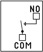
The SPDT Relay
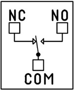 SPDT (Single Pole Double Throw) relays include three terminals: Common (COM), Normally Open (NO), and Normally Closed (NC)
- When the relay is off, COM is connected to NC.
- When the relay is energized, COM switches to NO.
2 Million+ Cycles
ProXR relays are built for longevity - expect years of reliable operation. The SPDT relay is rated for millions of mechanical cycles. Every board ships with a 5-year warranty and 30-day money-back guarantee.SPDT Relay Board
SPDT Relay Controller Specifications
This table outlines key performance ratings for all NCD SPDT Relay Controllers, based on 12VDC operation at 70°F (21°C). Many values are estimated and may be updated over time. Some ratings reflect standard, out-of-the-box settings without performance optimizations applied.Processing times can vary depending on background services and the commands you use. Standby power values assume no communication module is installed and no relays are active. For a more accurate power estimate, be sure to include the consumption of any installed communications module and any energized relays.
| Specs of NCD SPDT Relay Boards | Minimum | Nominal | Maximum | Notes |
| Operational Voltages | 10VDC | 12VDC | 15VDC | |
| Standby Power Consumption | 35mA | 100mA | 200mA | No Active Relays, No Com Module |
| Relay Power Consumption | 28mA | 35mA | 60mA | Consumption of Each Activated Relay |
| Operational Temperature Range | -40°F (-40°C) | 70°F (21°C) | 185°F (85°C) | Theoretical Component Limits Shown |
| Storage Temperature Range | -67°F (-55°C) | 70°F (21°C) | 185°F (85°C) |
Theoretical Component Limits Shown |
| Operational Ambient Air Humidity | 0% | 50% | 70% | Non-Condensing Humidity Values Shown |
| Relay Activation Time | 4ms | 5ms | 10ms | Needs Further Validation |
| Relay Deactivation Time | 5mS | 10mS | 15mS | Needs Further Validation |
Communication Modules
Communication Module Specifications
This table provides a quick, clear overview of all NCD Communication Modules. While each module operates at 3.3VDC, the values shown here reflect the impact on a 12VDC master controller at 70°F (21°C). Use the maximum ratings for power-budget planning - they represent short-term peak consumption and may include estimated values that are updated as modules evolve.| Specs of NCD Communication Modules | Minimum | Nominal | Maximum | Notes |
| Operational Temperature Range | -40°F (-40°C) | 70°F (21°C) | 185°F (85°C) | Theoretical Component Limits Shown |
| Storage Temperature Range | -67°F (-55°C) | 70°F (21°C) | 185°F (85°C) | Theoretical Component Limits Shown |
| Operational Ambient Air Humidity | 0% | 50% | 70% | Non-Condensing Humidity Values Shown |
| USB Module Power Consumption | N/A | N/A | N/A |
USB Modules are Powered by the USB Port Do Not Consume Device Current |
| RS-232 Module Power Consumption | 10mA | 20mA |
|
|
| Ethernet Module Power Consumption | 58mA | 82mA | 100mA | |
| WiFi Bluetooth USB Module Power Consumption | 37mA | 50mA | 100mA | Up to 300 Foot Indoor Wireless Range, Unobstructed. Up to 50 Foot Range Through Walls |
| 900MHz Wireless Module Power Consumption | 13mA | 30mA | 50mA | Up to 1,000 Foot Indoor Wireless Range, up to 2 Mile Outdoor Wireless Range using Included Antennas. Up to 28 Miles Outdoor Wireless Range using High-Gain Antennas. |
| KFX Wireless Key Fob | 11mA | 15mA | 25mA | Up to 200 Feet Outdoor Wireless Range using 1, 2, 3, 4, or 5 Button Key Fobs. Up to 700 Feet Outdoor Wireless Range using 8-Button Remotes |
A/D Inputs
AD8 Analog Input Usage Notice
Analog inputs should never have voltage applied when the controller is powered down. If your application requires voltage to remain on an input, add a 220-ohm current-limiting resistor to each channel to protect the controller from damage. Keep all analog inputs within the 0 - 5VDC range - exceeding this limit can permanently damage the on-board CPU. Most inputs include a 10K pull-up or pull-down resistor to keep the line stable when unused, but note that this resistor may introduce a slight bias in readings for certain sensors.Power Supply Available
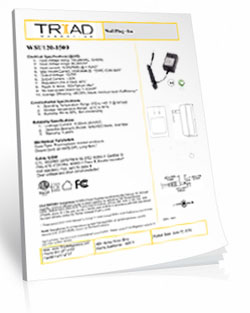
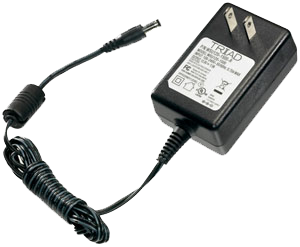 The PWR12 is regulated power supply providing clean power necessary for
the performance of these boards. The PWR12 US power supply is a 120VAC to 12VDC 1.25A 60Hz regulated
power supply and it plugs into the barrel connector on the board. The output connector is a 2.1mm I.D. x 5.5mm
O.D. x 9.5mm R/A barrel connector.
The PWR12 is regulated power supply providing clean power necessary for
the performance of these boards. The PWR12 US power supply is a 120VAC to 12VDC 1.25A 60Hz regulated
power supply and it plugs into the barrel connector on the board. The output connector is a 2.1mm I.D. x 5.5mm
O.D. x 9.5mm R/A barrel connector.
Click Here for More
Induction Suppression
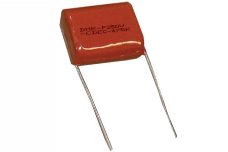 Controlling
an inductive load using our relay controllers requires the use of induction suppression capacitors. The purpose of this capacitor
is to absorb the high voltages generated by inductive loads, blocking them from the contacts of the relay. Without this capacitor,
the lifespan of the relay will be greatly reduced. Induction can be so severe that it electrically interferes with the microprocessor
logic of our controllers, causing relay banks to shut themselves down unexpectedly.
Click Here for More
Controlling
an inductive load using our relay controllers requires the use of induction suppression capacitors. The purpose of this capacitor
is to absorb the high voltages generated by inductive loads, blocking them from the contacts of the relay. Without this capacitor,
the lifespan of the relay will be greatly reduced. Induction can be so severe that it electrically interferes with the microprocessor
logic of our controllers, causing relay banks to shut themselves down unexpectedly.
Click Here for More
Relay Wiring Made Simple
From simple on/off switching to advanced AND/OR logic, these examples show exactly how to connect your relays for real-world applications. Learn the tricks to control lights, motors, sensors, and more with confidence.
Get a printout of this page
Relay Logic
"Using a light as an example load, let's wire to the board"
Relay Wiring Samples
This page provides simple examples showing how to wire a single relay - or multiple relays - for common switching applications. We use a light as the example load, but you can substitute a gate controller, security panel input, dry contact device, motor trigger, or most other switched loads. These wiring samples demonstrate different ways to connect relays to achieve the switching behavior you need.Relay Types
SPDT Relay
SPDT (Single Pole Double Throw) relays include three terminals: Common (COM), Normally Open (NO), and Normally Closed (NC).
- When the relay is off, COM is connected to NC.
- When the relay is energized, COM switches to NO.
Your load can be wired to either the NO or NC terminal depending on whether you want the device to turn on when the relay activates or when it releases. Examples below demonstrate both wiring methods. The SPDT relays offered on this site are 5-Amp, 10-Amp and 20-Amp models.
SPST Relay
SPST (Single Pole Single Throw) relays provide two terminals: Common (COM) and Normally Open (NO).
When the relay coil is energized, COM connects to NO to power the load. The only SPST relays offered on this site are our 30-Amp models. All SPDT examples shown on this page apply to these relays as long as the example does not require a Normally Closed terminal.
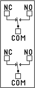
DPDT Relay
A DPDT (Double Pole Double Throw) relay contains two SPDT switches that operate together.
- Each side includes its own COM, NO, and NC terminals.
- Both internal switches change state at the same time.
This allows you to control two independent circuits with one relay. Wiring for each side of a DPDT relay follows the same rules as an SPDT relay, so the examples on this page apply directly. We offer the DPDT relays in 1-Amp, 3-Amp and 5-Amp models on ProXR boards starting at 8 relays.
Relay Grouping
Relay Grouping in the ProXR Command Set lets you combine individual relays to function like a DPDT relay using separate channels. This is ideal when you need to control multiple relays simultaneously or exceed the 5-Amp switching limit of our standard DPDT relays.Relay Logic Examples
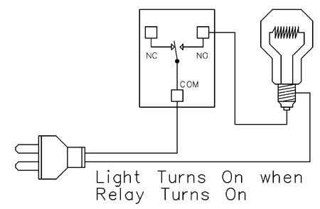
Example 1 - Simple Off/On Control
This example shows the most basic way to use a relay to switch a device such as a light. When the relay energizes, its NO (Normally Open) contact closes to COM (Common), completing the circuit and turning the light on.Only a single power wire is switched in this setup, making it the simplest method for controlling a light - or any device - using a relay.
Use this example for switching a light or any device you want to power only when the relay is on.
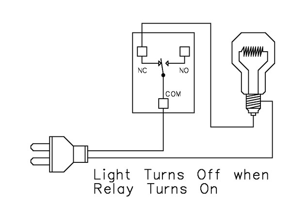
Example 2 - Simple On/Off (Using NC Contact)
This wiring method keeps the light on by default. The relay switches a single power wire through the COM (Common) and NC (Normally Closed) terminals.When the relay is not energized, the NC contact is closed to COM and the light remains on.
When the relay energizes, the NC contact opens, interrupting power and turning the light off.
This approach is ideal for devices that stay on most of the time, reducing relay wear since it doesn't need to remain energized to keep the device powered. It's also a useful method for power-cycling equipment - energizing the relay momentarily will turn the device off.
💡 Relay Pros ProTip:
For devices that stay on most of the time, use the NC contact. This reduces relay wear and extends the life of both the relay and your power supply.
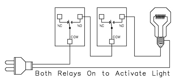
Example 3 - AND Logic Using Two Relays
 This example shows how two relays can work together so a light turns on only when both relays are energized. This creates an AND Logic condition:
Relay 1 AND Relay 2 must be on for the light to receive power.
A single power wire is switched, but it must pass through both relay contacts before reaching the light. This setup is ideal when two conditions must be met at the same time - such as requiring input from multiple sensors or system parameters.
MirC/MirX/MirM Users:
This wiring requires two contact closure inputs on the sender board before the receiver's relay activates. Use this approach when two independent outputs must close before turning on the light.For example, a light could turn on only when:
1. A light sensor detects it's dark AND
2. A motion sensor detects activity in the room
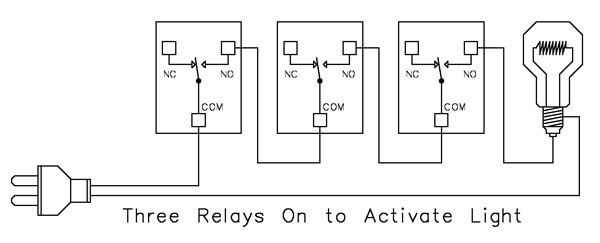
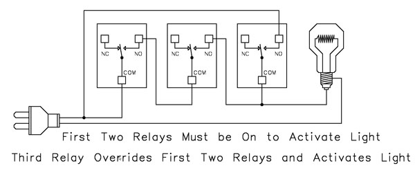
Example 4 - AND Logic Using Three Relays
 This example expands on the previous AND Logic concept. Here, the light will turn on only when all three relays are energized:
Relay 1 AND Relay 2 AND Relay 3 must be on for power to reach the light.
A single power wire is routed through all three relay contacts. Wiring from the NO (Normally Open) of Relay 1 to the COM (Common) of Relay 2, then from the NO of Relay 2 to the COM of Relay 3, creates a series path that requires every relay to energize before the light can activate.
This method can be scaled easily - just continue wiring NO of each relay to the COM of the next relay. Add as many relays as needed to meet your logic or safety requirements.
Example 5 - AND/OR Logic with Override
 This example demonstrates a combined AND/OR logic setup. The light will turn on when:
- Relay 1 AND Relay 2 are both energized OR Relay 3 is energized (override)
- For example:
- Relay 1 = night/day sensor
- Relay 2 = motion sensor
- Relay 3 = manual override (local switch)
A/D Board Users:
The Relay Activator function on any A/D board or ProXR Lite board lets you connect a button or switch to any A/D input. This input can then control the override relay, giving you a convenient local button to manually override the first two relays.MirC/MirX/MirM Users:
Add a manual button or switch to trigger the third relay when you need direct control instead of sensor-driven control.Reactor Users:
A local button or switch can be wired to the third relay input to provide a manual override for sensor-based logic.Example 6 - OR Logic (Either Relay Activates)
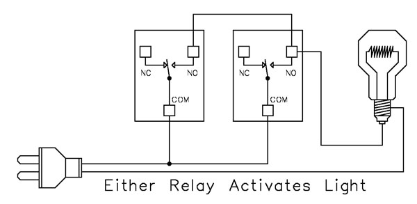 This example demonstrates OR Logic - the light will turn on when either relay is energized. Only one power wire is switched, but it can pass through Relay 1 or Relay 2 to reach the light.
- If Relay 1 activates, the light turns on
- If Relay 2 activates, the light turns on
- If both activate, the light remains on
- A timer controlling one relay, with a manual or secondary control for the other.
- Two sensors where either condition (motion detected or low light, for example) should activate the light.
A/D Board Users:
The Relay Activator function on any A/D board or ProXR Lite board lets you connect a button or switch to any A/D input. This input can then be used as a manual control of the relay.MirC/MirX/MirM Users:
Add a manual button or switch to trigger the third relay when you need direct control instead of sensor-driven control.MirC/MirX Users:
Wire two contact closure inputs into the sender board - either input can trigger the receiver relay to control the light.Example 7 - 3-Way Switch (Relay-Based 3-Way Control)
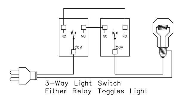 This example shows how to create a 3-way light switch setup using relays. A traditional 3-way circuit allows two switches to control the same light from different locations. In this wiring sample, each physical switch is replaced by a relay - but the operation is the same.
Only one power wire is switched, and the relays toggle the light depending on their current state.
- Activating either relay will toggle the light
- Activating both relays at the same time has the same effect as flipping both switches at once
Example 8 - DC Motor Direction Control
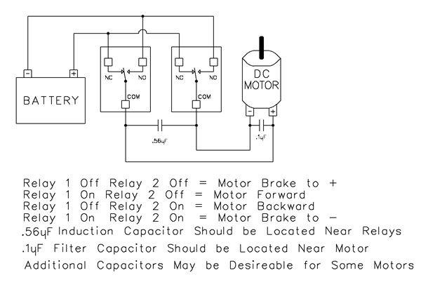 This example demonstrates how to control the direction of a DC motor using two relays. By changing how the motor's leads connect to power, you can run the motor forward, reverse, or place it in a brake state. Braking is achieved by tying both motor terminals to the same power connection, which stops rotation through Faraday's Law.
- Relay Operation Summary
- Relay 1 Off / Relay 2 Off → Motor Brake to +
- Relay 1 On / Relay 2 Off → Motor Forward
- Relay 1 Off / Relay 2 On → Motor Reverse
- Relay 1 On / Relay 2 On → Motor Brake to -
- The induction suppression capacitor prevents the relay from shutting off due to motor back-EMF
- The 0.1µF filter capacitor reduces electrical noise, especially useful when powering sensitive electronics such as radios or amplifiers.
- Capacitor Placement
- Place the induction suppression capacitor near the relays
- Place the filter capacitor near the motor
- Additional capacitors may be needed for certain motors
Motors draw significantly more current at startup than during continuous operation - often 2-3 times their rated running current. For example, a motor rated at 5A (125VAC) may require 10-15A to begin turning. Always select a relay that exceeds the motor's initial inrush current, not just its running current. In this case, a 20-30A relay provides optimal performance and longevity.
💡 Relay Pros ProTip:
Motors and inductive loads often draw 2-3x their rated current at startup. Always choose a relay that exceeds the motor's inrush current, not just its running current.