WiFi Push Notification 2-Input with Wi-Fi Interface
MIRCC2_WiFi
WiFi Push Notification
The MIRCC2_WiFi WiFi Push Notification board allows you to monitor two dry contact inputs and automatically send individual text and/or email notifications when either input changes state.N-Button Software monitors the board input through your wireless network and sends notifications to one or multiple recipients, making the board ideal for equipment alarms, warning systems, machine status monitoring and process notifications.
In most applications, all that's required is a simple dry contact closure output from the equipment or device being monitored.
NexGen WiFi Interface
The onboard NexGen Wi-Fi interface connects the board to your existing 2.4GHz wireless network. The interface supports IEEE 802.11 b/g/n Wi-Fi communication standards along with WPA/WPA2 security, WPA2-Enterprise authentication and Soft AP web-based configuration.
- OVERVIEW
- Wi-Fi Interface
- Board Features
- N-Button Software
- NextGen PUSH SETUP
- ACCESSORIES
- Data Sheets
Wi-Fi Push Notification at a Glance
- Push Notification Inputs
- 2 Contact Closure (No Voltage) Inputs
- 12 Guage Solid Core Wire Capacity
- Compatible with any Contact Closure Sensor
- Temperature Rating -40° C to 85° C - Embedded WiFi over 802.11b/g
- 2.4GHz WiFi Communications IEEE 802.11 b/g/nr
- Security: WPA/WPA2/WPA2-Enterprise and WPS
- Supports DHCP or Static IP
- Soft AP Web Interface for Configuration - N-Button Software
- Monitors Input
- Send SMS and/or Email Message
- Point & Click Interface
- Use to Configure Messages
- Unique Message for Each Input
- No Monthly Fees
)
Simple 3-Step Setup
1-Connect the board to your network and configure communication settings.
2-Create a Scan Channel in N-Button Software to monitor the board inputs.
3-Configure text and/or email notifications for each input you want to monitor.
Wi-Fi Push Notification
"Read outputs over your WiFi Network"
NexGen WiFi Interface
The WiFi Push Notification board communicates with N-Button Software through your existing wireless network, eliminating the need to run Ethernet cables between the board and your computer.Once connected to your WiFi network, the board communicates using an assigned IP address, allowing N-Button Software to monitor inputs and send notifications from anywhere on your local network.
The NexGen WiFi interface supports 2.4GHz IEEE 802.11 b/g/n wireless networks along with WPA/WPA2 security and WPA2-Enterprise authentication.
NexGen WiFi Communications Module
 This board is equipped with the NexGen WiFi communications module, providing reliable wireless communication between the Push Notification board and N-Button Software.
 Configuration is performed using the built-in Soft AP web interface, allowing setup from a smartphone, tablet, laptop or desktop computer with WiFi capability.
Once configured, the board automatically reconnects to the wireless network whenever power is restored.
Network Configuration
The NexGen WiFi module supports both DHCP and Static IP addressing for easy integration into existing network environments.Advanced configuration options including communication ports and network settings are available through the integrated Soft AP web interface.
💡 Relay Pros ProTip:
If a wired network connection is available, Ethernet is typically the easiest network interface to configure. WiFi is ideal when running network cables is impractical or impossible.
Know When Equipment Changes State
Receive instant text and/or email notifications when equipment alarms, warnings or monitored inputs change state.
Push Notification boards help eliminate missed alarms by turning dry contact outputs into real-time notifications for owners, maintenance and system administrators.
The Push Notification Board
"Convert dry contact outputs into real-time alerts."
The Push Notification Board
Push Notification boards are designed to monitor dry contact closure inputs and automatically trigger text and/or email notifications when an input changes state.The board communicates with N-Button Software through the selected USB, Ethernet or WiFi interface where notifications can be configured for one or multiple recipients.
In most applications, all that's required is a simple dry contact closure output from the equipment or device being monitored.
Is your equipment trying to tell you something?
Many industrial devices provide dry contact closure outputs specifically for alarms, warnings and status monitoring. Push Notification boards allow you to monitor those outputs and automatically send text and/or email notifications when something changes.The Input Side
"Where the board gathers information."
Dry Contact Inputs
Inputs on Push Notification boards are compatible with dry contact closure devices such as:- Pushbuttons
- Toggle switches
- Float switches
- Relay outputs
- Alarm contacts
- Sensors and monitoring devices
Simple Input Wiring
The board includes screw terminal input connections for easy installation and field wiring.Inputs are designed for dry contact closure only and may be connected to virtually any device capable of providing a no-voltage dry contact output.
Inputs on Push Notification boards are designed for dry contact closure signals only. Never apply external voltage directly to an input terminal, as damage to the board may occur.
Board Features
"What sets us apart."
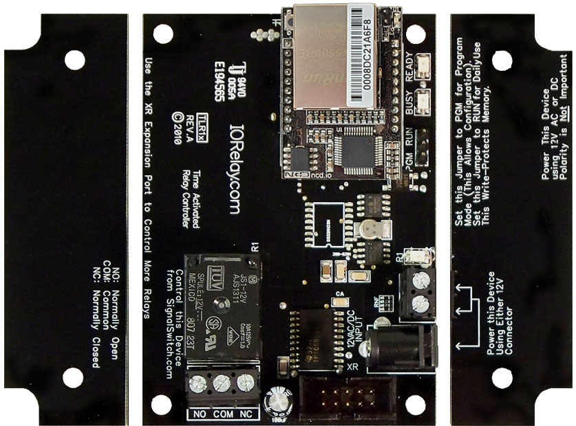
Break-A-Way Tabs for a Smaller Design
Need a smaller footprint? The Push Notification PCB includes Break-A-Way Tabs, allowing the board to fit into optional undrilled enclosures or tight-space installations.
RoHS Compliant & Lead-Free
All Push Notification Boards are built with RoHS-compliant components and lead-free solder.Power & Protection
"Reliable Power = Reliable Notifications"
Essential Power Requirements
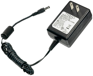 Clean, regulated power is critical.
A stable 12VDC supply ensures both the relay coils and onboard firmware operate correctly. Unstable or noisy power can cause improper reading or communication issues.
We recommend the PWR12-US (120VAC → 12VDC @ 1.25A) or our international supply with interchangeable adapters.
Learn More
Support & Ownership
"5-year warranty & no monthly subscriptions."
5-Yeary Warranty & Guarantee
Every Push Notification Board is covered by:- 5-Year Functional Warranty
- 30-Day Money-Back Guarantee
- No Monthly Subscriptions
Shipping
All boards ship directly from our Missouri facility. Each unit is built and tested at the time of order - please allow 3 - 5 days for production. We ship primarily through UPS, but we're happy to use FedEx or DHL for international orders when you provide your account number. Questions? Call us at 800-960-4287 or email sales@relaypros.com.Developer/API
Direct Query Command Set
For custom software applications, Push Notification boards may also be monitored directly through software commands instead of N-Button Software.- Decimal Values: 254 (Command) 150-157 (Parameter - Channel 1-8)
- Hex Values: 0xFE (Command) 0x96 - 0x9D (Parameter - Channel 1-8)
- Receive Byte: Decimal: 0-255, Hex: 0x00-0xFF
Configuring the Software
Setting up Push Notification with N-Button:
✔-Once you've established communication with the board
2-Create a Scan Channel in N-Button Software to monitor the board inputs.
3-Configure text and/or email notifications for each input you want to monitor.
Push Notification with N-Button
"Turn equipment status signals into notifications with N-Button."
N-Button Software
N-Button Pro/Lite Software is the monitoring and notification platform used with Push Notification boards.Using a simple point-and-click interface, N-Button allows you to monitor dry contact inputs, configure text and email notifications, create visual status indicators and automate actions based on equipment status changes.
Each monitored input can have its own custom notification message, recipient list, visual indicator and automation rules, making the software ideal for equipment alarms, security monitoring, process alerts and unattended systems.
There are no monthly subscription fees for N-Button Software. Notification limits are based only on the email or SMS provider being used.
Scan Channels
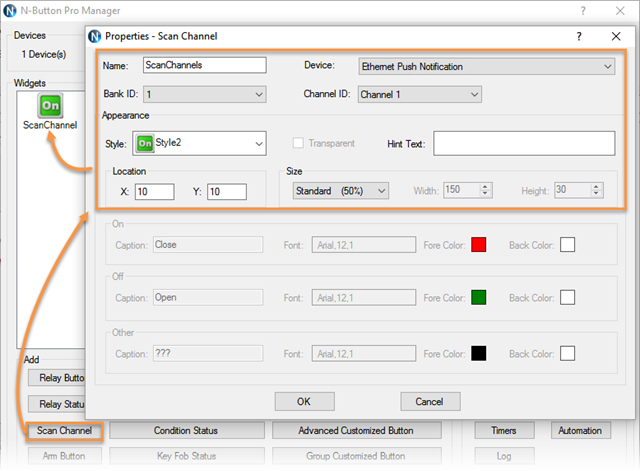
Scan Channels are the core of the Push Notification monitoring system.A Scan Channel continuously monitors an input on the Push Notification board and determines whether the dry contact circuit is open or closed.
When the input changes state, the Scan Channel processes the event and can trigger text notifications, email alerts, visual indicators and automation actions within N-Button Software.
A separate Scan Channel is typically created for each input on the board, allowing every monitored device or alarm condition to have its own notification settings and visual status indicator.
Monitor Inputs From Your Desktop
 When a Scan Channel is created, N-Button will place place a visual status widget directly on the desktop of your computer. The widget continuously reflects the current state of the monitored dry contact input using user-defined colors for both the open and closed conditions.
 This provides a simple real-time visual indication for monitoring doors, gates, alarm contacts, equipment status signals, tank levels and other connected sensors.


Desktop monitoring can be used by itself for visual status indication or combined with text and email notifications for complete alarm monitoring and response.
Gmail & Email Setup
N-Button Software sends notifications using standard email accounts such as Gmail and other SMTP-compatible providers.Email notifications are sent directly to the recipient's email address. SMS notifications are typically sent using an Email-to-SMS Gateway Address provided by the recipient's mobile carrier. Instead of entering only a phone number, SMS recipients are configured using the carrier's Email-to-SMS Gateway Address, which converts the email into a text message delivered to the mobile device.
A single notification can be sent to multiple email addresses, SMS recipients or a combination of both.
For Gmail accounts, Google App Passwords are required when 2-Step Verification is enabled. Step-by-step setup information is included in the detailed setup guides below.
SMS notifications are typically delivered using your mobile carrier's Email-to-SMS Gateway service. Simply enter the gateway address provided by the carrier and N-Button will send the notification as a text message.
Send SMS, Email or Both
N-Button Software can send text notifications, email alerts or both simultaneously when a monitored input changes state.Custom subjects and messages may be configured for each input so recipients know exactly which alarm, sensor or piece of equipment triggered the notification.
💡 Relay Pros ProTip:
Notifications can be configured to repeat at specific intervals until the alarm condition clears. For example, if a freezer temperature alarm triggers a dry contact output, text and email alerts can continue being sent to maintenance personnel until the temperature returns to normal.
Automation & Relay Control
Control Actions from Inputs
N-Button Software can also trigger actions based on input status changes.Using Automation Rules, Push Notification board inputs can control relays on compatible relay boards to activate warning lights, buzzers, sirens, fans or other connected equipment automatically.
For example, when an alarm contact closes, N-Button can simultaneously:
- Send text and email notifications
- Display a visual alarm on-screen
- Activate a warning light or buzzer
- Control relays on additional boards
💡 Relay Pros ProTip:
If your application also requires relay control, ProXR Lite relay boards can provide an all-in-one solution. ProXR Lite boards include onboard relays along with A/D inputs capable of monitoring dry contact closures, allowing the same board to read inputs and control relays simultaneously.
Need More Information?
Detailed step-by-step guides for to conntact each interface and setting up N-Button software.USB Push Notification Setup
Ethernet Push Notification Setup
WiFi Push Notification Setup
Power Supply Available
 The PWR12 is regulated power supply providing clean power necessary for
the performance of these boards. The PWR12 US power supply is a 120VAC to 12VDC 1.25A 60Hz regulated
power supply and it plugs into the barrel connector on the board. The output connector is a 2.1mm I.D. x 5.5mm
O.D. x 9.5mm R/A barrel connector.
The PWR12 is regulated power supply providing clean power necessary for
the performance of these boards. The PWR12 US power supply is a 120VAC to 12VDC 1.25A 60Hz regulated
power supply and it plugs into the barrel connector on the board. The output connector is a 2.1mm I.D. x 5.5mm
O.D. x 9.5mm R/A barrel connector.
Click Here for More
Enclosure Available
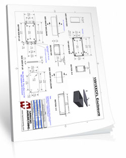
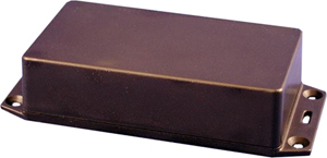 The CFL Enclosure is an undrilled, non-waterproof enclosure and is available at checkout for this controller.
CFL Spec Sheet
CAD Drawing: CFL CAD Drawing
3D Model: CFL_3D
N-Button Lite
 N-Button
Lite is software will read the two inputs on the board and send out the text and/or email message. You can configure seperate text and/or email
for each input and send them to multiple recipients! For detailed instructions on setting up the board and messages
Click Here!
N-Button
Lite is software will read the two inputs on the board and send out the text and/or email message. You can configure seperate text and/or email
for each input and send them to multiple recipients! For detailed instructions on setting up the board and messages
Click Here!
Push Notification Setup
There is some setup required to get the board on your network and to setup N-Button Software to communicate to the board. Take a look at the instructions on this tab to see what is involved in setting up the board.
NextGen Push Setup
"Add board to network, setup ScanChannel, start monitoring"
NextGen WiFi Setup
The NexGen WiFi module includes a built-in web interface that makes connecting the Push Notification board to your wireless network straightforward.Some initial configuration is required, but most users are up and running in just a few minutes using a phone, tablet or computer.
Simple Guided Configuration
When powered on in configuration mode, the NexGen module creates its own temporary WiFi network. Simply connect to the module, open the built-in configuration page and enter your WiFi network information. During setup you will:
- Connect the module to your WiFi network
- Choose DHCP or a Static IP Address
- Enable N-Button communications
- Save your settings and restart the module
💡 Relay Pros ProTip:
If a wired network connection is available, Ethernet is typically the easiest network interface to configure. WiFi is ideal when running network cables is impractical or impossible.
N-Button Communication Setup
After the board is connected to your WiFi network, it must be added to N-Button Software using Device Manager.N-Button will automatically discover compatible Push Notification boards on your network, allowing you to quickly add the device and begin monitoring inputs.
Once the board has been added, create a Scan Channel for each input you wish to monitor. Scan Channels continuously monitor input status and can trigger notifications, visual indicators and automation actions whenever an input changes state.
Need More Information?
Detailed step-by-step guide for The WiFi Push Notification board and N-Button software.WiFi Push Notification Setup