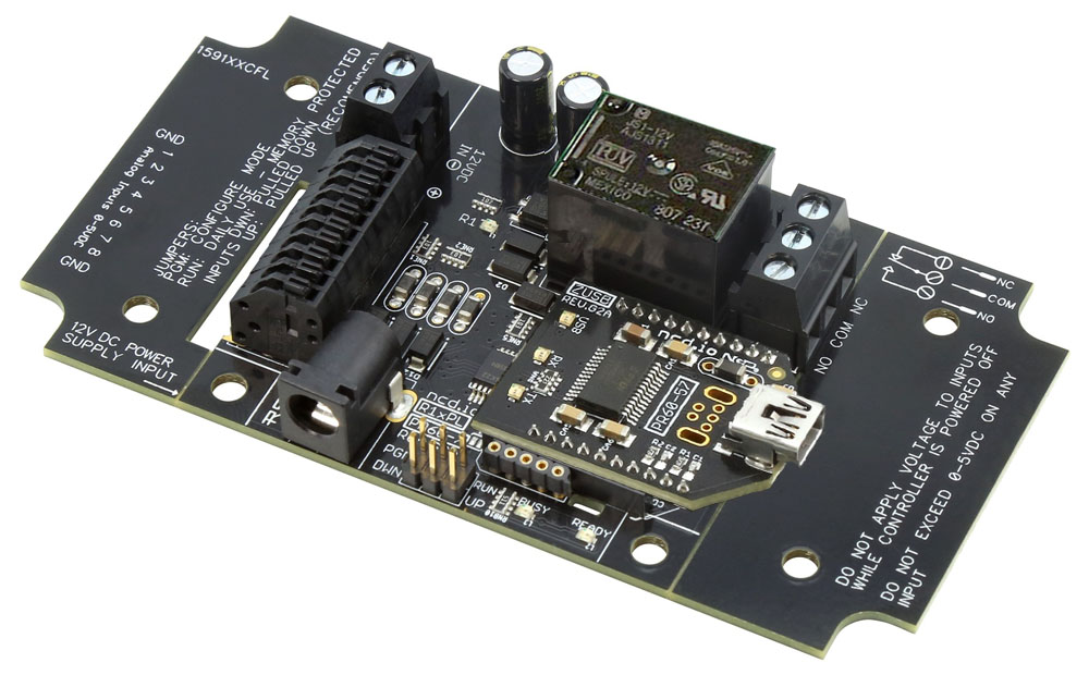
USB Relay 1-Channel 5-Amp ProXR Lite
R15PL_USB
USB Relay
Our USB interface module makes relay control effortless. Just plug it into any available USB port and start controlling relays or reading A/D inputs with simple serial commands. Every NCD USB module uses a genuine FTDI USB-to-Serial converter chips - the industry standard for speed, stability, and compatibility.Communicate with the board through a virtual COM port, making software integration straightforward across nearly any programming environment.
The ProXR Command Set
The R15PL_USB uses the ProXR Command Set for simple yet powerful control. Send basic commands to turn relays on or off, or take advantage of advanced features like delays, flashers, duration timers, and full relay-status feedback. From quick automation scripts to full system integrations, ProXR commands deliver a proven, reliable command set trusted across the industry.
- OVERVIEW
- USB Interface
- Board Features
- ProXR Command Set
- AD8 Command Set
- Power & More
- Relay Logic
- N-Button Lite
- Base Station
- Software
- Induction
- ACCESSORIES
- Data Sheets
USB Relay at a Glance
- 1 5-Amp Relay Installed
- Single Pole Double Throw (SPDT) Relay
- Wire to Normally Open or Normally Closed Position
- 12 Guage Solid Core Wire Capacity
- Temperature Rating -40° C to 85° C
- Not-Expandable - Onboard USB Interface Module
- Connects Directly to a USB Port
- Mounts as a Virtual COM Port for Seamless Integration - Industry-Leading ProXR Command Set
- Program in Nearly Any Language
- Send Precise Relay Commands
- Toggle, Flash, and Timing Control - ProXR AD8 Command Set (Input Support)
- Read 0-5V Sensors
- Monitor External Sensors or Contact Closure
- Use Inputs to Trigger Relays
)
FTDI Driver
The FT232RL mounts as a standard COM port on Windows, macOS, and Linux once the appropriate FTDI drivers are installed. This Virtual COM Port interface is widely supported and highly reliable. FTDI chips remain the industry leader for compatibility, stability, and long-term performance.
http://www.ftdichip.com/FTDrivers.htm
USB Relay Control
"Send commands via your computer's USB port"
Mounts as a Virtual COM Port
The USB Relay connects directly to your computer's USB port and appears as a standard COM port. On Windows machines with internet access, the correct FTDI drivers install automatically.Once powered, the board listens for compact serial commands - typically 2 - 6 bytes. After processing your command, it returns ASCII code 85 to confirm successful completion.
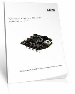
USB Communications Module
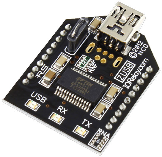 The USB Relay module makes controlling relays simple. Plug it into any available USB port and begin sending standard serial commands to switch relays or read A/D inputs.
Every NCD USB interface uses a genuine FTDI FT232-RL USB-to-Serial converter chip for maximum stability and cross-platform support. With drivers available for Windows, macOS, Linux, and more, the module communicates using a Virtual COM Port for easy software integration.
Once installed, open the COM port at 115.2K baud and start exchanging data immediately. On-board USB, TX, and RX LEDs provide live communication feedback. The module uses a durable USB Mini connector - our preferred interface for longevity and reliability.
Simply download the latest Base Station Software, install it on your Windows PC, and your COM port will appear automatically, ready for communication.
Virtual COM Port
 A Virtual COM Port (VCP) registers as a standard serial port on your computer, allowing you to use new or existing serial-based software with any NCD Industrial controller.
Because VCP communication is one of the easiest and most universally supported communication formats across operating systems, languages, and hardware platforms, the ZUSB USB Interface is the ideal tool for learning, testing, and operating NCD devices.
Induction Considerations
For most applications, the onboard capacitors provide more than enough suppression, and users will never encounter communication issues.However, switching inductive loads such as motors can create higher levels of electrical noise, and in those situations additional precautions may be necessary. Testing is recommended for motor-based installations to ensure reliable communication.
If communication problems do occur in these high-induction environments:
- An RS-232 communications module provides a more noise-resistant interface.
- When USB connectivity is still needed, a USB-to-RS-232 adapter paired with the RS-232 module offers the stability of RS-232 with the convenience of USB.
- RS-232 naturally blocks induction to safer levels, allowing the adapter to operate without errors even in demanding motor-control setups.
USB Relay Videos
Simple, Reliable Relay Control
ProXR Lite boards are built for dependable, no-nonsense relay control. You get industrial-grade hardware, the full ProXR command set, built-in analog inputs, and long relay life - without expansion complexity or unnecessary extras.
The ProXR Lite SPDT Relay Board
"Built for Reliability. Engineered for Simplicity"
ProXR Lite Relay Design
The ProXR Lite series is machine-manufactured for consistent, high-precision performance. Every controller is fully tested before it leaves the production floor, ensuring dependable operation in tough environments - heat, cold, vibration, and everything in between. With thousands of units in the field worldwide, these boards have proven they can take a beating and keep on switching.ProXR Command Set
You get access to a huge library of functions, timers, parameters, and control options - all programmable in nearly any language. Prefer no-code? Software is available, too.
Find the full command set in the ProXR Enhanced Quick Start Guide.
Easy Software Development
Most customers write their own control programs, and the ProXR Lite makes that easy.Because the board uses the Serial Port Profile, it mounts as a virtual COM port, allowing simple command-based control from nearly any programming language.
Not a programmer? N-Button Lite offers point-and-click relay control and status monitoring - no code required. Click Here for More
Read Analog Sensors
 Every ProXR Lite board includes an 8-Channel 8/10-Bit A/D Converter.
Monitor up to eight sensors from 0 - 5VDC (0V can be read from a simple contact closure). Use A/D inputs for:
- Switch status monitoring
- Variable resistance sensors
- Simple automation logic
See the AD8 Quick Start Guide for full A/D command documentation.
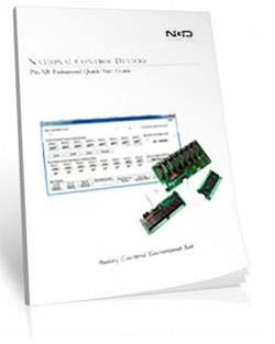
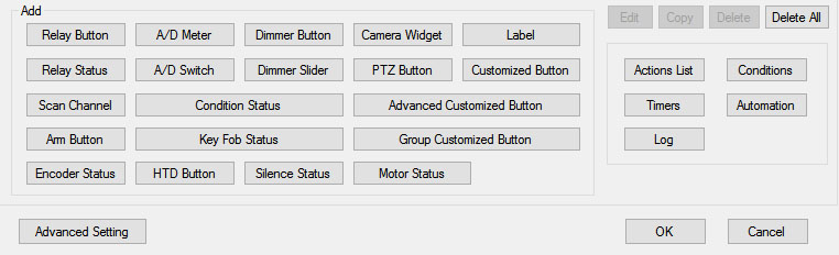
Relay Activator and Analog Inputs
The Relay Activator control panel lets you use analog inputs to directly control onboard relays. Just connect buttons or switches to the analog inputs and trigger simple on/off actions for manual relay control. Each of the eight inputs can be assigned one of eight functions, including turning relays on or off, toggling relay states, flashing a relay momentarily, toggling the flash function, turning all relays on, turning all relays off, or generating push-notification events using N-Button Software. Click the gray Relay Logic tab and check out Example 6 to see how to wire a manual switch into your setup. Download the Relay Activator Quick Start Guide here: Relay Activator Quick Start Guide.SPDT Relay Installed
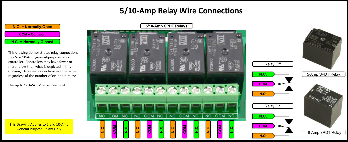
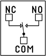 SPDT (Single Pole Double Throw) relays include three terminals: Common (COM), Normally Open (NO), and Normally Closed (NC)
- When the relay is off, COM is connected to NC.
- When the relay is energized, COM switches to NO.
2 Million+ Cycles
ProXR relays are built for longevity - expect years of reliable operation and millions of mechanical cycles. Every board ships with a 5-year warranty and 30-day money-back guarantee.Not Expandable (By Design)
ProXR Lite keeps things simple.Unlike the full ProXR Series, Lite boards do not support relay expansion. While the firmware still reports up to 256 potential relays, only the first 1, 2, 4, or 8 relays in Bank 1 are active depending on the model you choose.
💡 Relay Pros ProTip:
ProXR Lite boards are perfect when you only need a few relays and don't plan to expand later. You still get the full ProXR command set - just in a simpler, cost-effective package.
Break-A-Way Tabs for a Smaller Design
Need a smaller footprint? The ProXR Lite PCB includes Break-A-Way Tabs, allowing the board to fit into optional undrilled enclosures or tight-space installations.
RoHS Compliant & Lead-Free
All ProXR Lite controllers are built with RoHS-compliant components and lead-free solder.5-Yeary Warranty & Guarantee
Every ProXR Lite controller is covered by:- 5-Year Functional Warranty
- 30-Day Money-Back Guarantee
Essential Power Requirements
 Clean, regulated power is critical.
A stable 12VDC supply ensures both the relay coils and onboard firmware operate correctly. Unstable or noisy power can cause improper switching or communication issues.
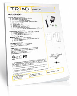
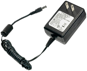
We recommend the PWR12-US (120VAC → 12VDC @ 1.25A) or our international supply with interchangeable adapters.
Learn More
Shipping
All boards ship directly from our Missouri facility. Each unit is built and tested at the time of order - please allow 3 - 5 days for production. We ship primarily through UPS, but we're happy to use FedEx or DHL for international orders when you provide your account number. Questions? Call us at 800-960-4287 or email sales@relaypros.com.Induction Suppression
 One of the most important parts of relay control - yet the most commonly overlooked - is inductive load protection.
Anything with a magnetic coil (motors, solenoids, transformers, etc.) generates high-voltage "kickback" when switched. Without a suppression capacitor, that spike can:
- Shorten relay lifespan
- Cause electrical noise that disrupts the microcontroller
- Trigger unexpected shutdowns
- Require power cycling to restore communication
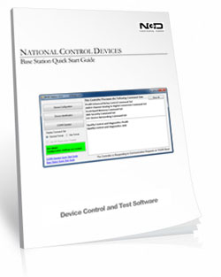
Base Station Software
Base Station is the fastest way to learn and control the ProXR Lite board. Explore every feature through an intuitive GUI while watching live data flow to and from the board.Designed to work seamlessly with the entire family of communication modules, Base Station supports every feature the board offers - far beyond what other manufacturers provide. More on Base Station can be found in the Base Station tab.
ProXR Lite at a Glance
A more streamlined manufacturing process brings a more durable, reliable and better relay board to the market. Here's a lists of great features:
- User Friendly Board Design
- Single Pole Double Throw Relays Installed
- Wire to Normally Open or Normally Closed Position - Break-A-Way Tabs Lets you Decide the Board's Size
- Screw Terminal Contact Closure/Relay Connections
- RoHS Compliant
- ProXR Lite Features
- Industry Leading ProXR Command Set
- 8-Channel 8/10-Bit Analog to Digital Converter
- Highly Reliable Board
- Assign up to 16 Programmable Timers
- ProXR Lite Limitations
- Not expandable (fixed relay count)
Powerful Control, Any Language
The ProXR Command Set gives you precise, reliable control using simple serial commands - compatible with nearly any programming language. Use it directly in your own software or explore every feature using free configuration tools.
The ProXR Command Set
"The industry's most powerful relay command set"
Simple Serial Commands. Serious Control.
The ProXR family of controllers is driven by a powerful, low-level serial command set. You send a short numeric or Hex command to the board - and the board responds immediately.This design keeps your software fast, reliable, and easy to integrate into almost any platform, from small scripts to full automation systems.
How to Send Commands
You can send commands as:
- Decimal byte values
- Hex byte values
What a Command Looks Like
At its simplest, a relay command is only three bytes:254 108 1 - Turn ON relay 1 in bank 1
0xFE 0x6C 0x01 - If you require Hex
254 100 1 - Turn OFF relay 1 in bank 1
0xFE 0x64 0x01 - If you require Hex
The controller processes the command and returns a confirmation byte 85 (0x55 Hex) when the operation completes.
💡 Relay Pros ProTip:
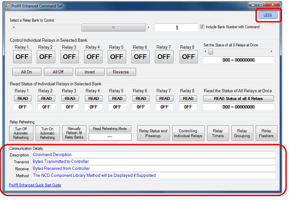
Let Base Station Show You the Command! Base Station software can show you the exact command being sent to the controller. Click the More button in the upper-right corner of the Base Station window to expand the interface and display the command output. When you control relays using the point-and-click interface - turning relays on or off, toggling outputs, or using timing and flasher functions - Base Station displays the actual command being transmitted to the board.
This is extremely useful for programmers. You can perform the function you want in your application and instantly see the decimal or hexadecimal command - the same command you'll use in your programming.
Relay Banks - How Large Systems Stay Simple
ProXR and ProXR Lite controllers organize relays into groups of eight called banks.Each bank contains:
- Relay 1 through Relay 8
Expandable ProXR boards use the same bank structure, but can add additional banks using XR expansion boards as your system grows.
For example:
- An 8-relay controller uses one bank
- A 32-relay controller uses four banks
- A 64-relay setup uses eight banks
- Select a bank
- Send simple relay commands within that bank
Two Ways to Address Relays
You can control relays in two different (and complementary) ways:- Current Bank Commands - select a bank once, then issue fast relay commands
- Bank-Directed Commands - specify the bank directly inside the command
For larger installations, bank-directed commands make software logic easier and more robust.
What You Can Do With the ProXR Command Set
The ProXR command set is designed to support real automation projects - not just basic relay switching.Common operations include:
- Turn individual relays on or off
- Turn multiple relays on or off in a single command
- Read the on/off status of any relay
- Control relays by bank for large systems
- Read analog sensor values (A/D inputs)
- Assign and control internal timers
- Trigger relay pulses and timed operations
- Use onboard logic features such as the Relay Activator system
Designed for Any Programming Language
Because the ProXR command set is pure byte-based serial communication, you can use it from:- Python, C#, C++, Java, Node, LabVIEW, and PLC environments
- Embedded controllers and microcontrollers
- Industrial automation and building control systems
No-Code and Learning Tools
If you do not want to write software immediately, free tools are available:- Base Station Software - explore every command, watch live data, and test automation logic
- N-Button Software - create buttons and automation actions without writing code
Full Command Reference
This page is intended as a high-level overview of how the ProXR command system works. For the complete command reference, including all relay, bank, timer, and analog input commands, download the official guide:ProXR Enhanced Quick Start Guide
Relay Grouping - Switch Multiple Relays at the Exact Same Time
Control Neighboring Relays
Relay Grouping lets you control multiple neighboring relays as one logical output.Think of it like building your own multi-pole relay:
- 2 relays → act like a DPDT
- 3 relays → act like a 3PDT
- ...
- up to 8 relays at once in the same bank
How it Works
Relay Grouping adds one extra value to a normal relay command called the Neighbor parameter.The Neighbor value simply means: "Also apply this same command to the next 1-7 relays."
So instead of turning on just one relay...
you turn on that relay plus its neighbors in one shot.
Neighbors must stay inside the same relay bank
For example:- Relay 1 can have up to 7 neighbors
- Relay 8 has no neighbors, because the next relay is in the next bank
💡 Relay Pros ProTip:
Relay Grouping is perfect when you need multiple contacts to move together but still want the flexibility of individual relays also. Instead of hunting for odd multi-pole relay hardware, you can build exactly the behavior you need in firmware.
And if your design changes later? You're not locked into a special relay block.
Prevent Overlapping Relay States
Safe Break-Before-Relay Switching
Some applications require more than simply turning a relay on or off. When controlling motors, actuators, gates, shades, and door systems, it's critical that two opposing relays are never active at the same time.The ProXR firmware includes a built-in Break-Before-Relay command that:
- Turns all relays off
- Waits a short, controlled delay
- Then turns only the selected relay on
Break-Before-Relay Command Example
This example performs a safe switch operation and then activates the selected relay.Decimal: 254 46 0 0
Hex: 0xFE 0x2E 0x00 0x00
When the operation completes, the controller returns: 85 (0x55)
💡 Relay Pros ProTip:
This command is a game-changer for motor control. Use it for gate operators, door controllers, window shades, linear actuators, and any system that uses one relay for "forward" and another for "reverse". By forcing all relays off before energizing the next relay, you protect the motor from being driven in two directions at the same time - a common cause of overheating and motor failure.
This safety behavior is handled entirely inside the ProXR firmware, so your software does not need to manage timing or relay interlocks.
Relay Timers
Relay Timers - Built-In Time Control
ProXR controllers include 16 built-in relay timers that let you turn a relay on for a specific amount of time - without your software having to turn it back off.This is perfect for applications such as:
- Door strikes and mag-locks ("buzz someone in")
- Key-card and access control systems
- Gate and barrier controllers
- Lighting and automation events
Two Simple Timer Modes
ProXR relay timers support two easy-to-use modes:- Duration - turns a relay ON for a specified time, then turns it OFF automatically
- Pulse - waits for the timer to expire, then briefly activates a relay
Simple Duration Timer (Most Common Use)
A duration timer turns a relay ON, holds it ON for the programmed time, and then turns it OFF automatically.You can program:
- Hours
- Minutes
- Seconds
Duration Timer Command Example
Send Bytes (Decimal): 254 50 50 0 0 5 0Send Bytes (Hex): 0xFE 0x32 0x32 0x00 0x00 0x05 0x00
This example activates a relay for 5 seconds, then turns it off automatically.
When the command completes, the controller returns: 85 (0x55)
💡 Relay Pros ProTip:
Relay timers are ideal for door strikes and access control. Instead of having your software turn the relay off, simply send a duration timer for 2-10 seconds. The relay releases the lock, lets the person through, and automatically re-locks the door - even if your software is busy or momentarily disconnected.
Timing is handled inside the ProXR firmware, so your application only needs to send a single command to perform the entire operation.
Note: ProXR controllers do not include a real-time clock. Timers are intended for event-based timing (such as opening a door for a few seconds), not for scheduled calendar-based automation.
Relay Flashers
Relay Flashers - Built-In Blinking and Pulse Control
ProXR controllers include a powerful background relay flasher engine. Once a relay is assigned to a flasher, the firmware automatically turns that relay on and off for you - no software timing loops required.This is ideal for:
- Status indicators and stack lights
- Warning beacons and alarms
- Heartbeat and activity indicators
- Simple pulse or attention signals
Set the Flash Rate (All Flashers)
You can set the flash speed for all active relay flashers with a single command. The speed parameter ranges from 0-255, where:- 0 = fastest flash rate
- 255 = slowest flash rate
Decimal: 254 45 0 128
Hex: 0xFE 0x2D 0x00 0x80
When the command is accepted, the controller returns: 85 (0x55)
💡 Relay Pros ProTip:
Flashers are perfect for visual feedback. For example, use a flashing relay to indicate "system running", "waiting for input", or "fault detected" - while your main software continues doing real work.
Flasher commands can also be combined with relay timers and other ProXR features inside Base Station, making it easy to build pulse, blink, and notification behavior without writing custom timing code.
Base Station Software
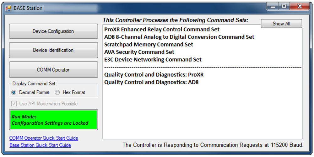
Device Command Sets
 Base Station asks the controller which command sets it supports, then displays them when the software launches. Some devices show more command sets, others fewer - it's always based on the board.
ProXR users can access the entire ProXR Command Set to turn relays on/off and run every available function.
Control All ProXR Functions
Turn relays on or off, read relay status, monitor inputs - Base Station gives full ProXR control through a clean point-and-click interface.For programmers, Base Station also shows every command being sent to the board, making it a great tool for learning and development.
Useful Features
There are some useful features to look for when using Base Station Software to control, test, or configure your device:- Links to Quick Start Guides and documentation
- Discovery of network devices with IP address display
- Command Set Window for viewing raw commands (especially helpful for ProXR users)
- Relay Activator with Analog Inputs
Turn Sensors into Actions
Built-in analog inputs let you read switches and 0-5V sensors in real time - and automatically trigger relays, alerts, or automation rules. Monitor data, control outputs, or send notifications using software tools, with no extra hardware required.
The AD8 Command Set
"This isn't just a relay board - it's a control system."
Reading Switches/Variable Resistance Signals
This controller includes eight channels of 8/10-bit Analog-to-Digital Converters capable of reading 0 - 5V DC signals. The ADCs allow you to monitor external sensors or detect contact-closure inputs. Connect temperature sensors, light sensors, current sensors, buttons, switches, or any device that outputs a 0 - 5V signal or simple contact closure.- With 8-bit resolution, inputs convert 0 - 5V into values from 0 to 255
- With 10-bit resolution, values range from 0 to 1023
A/D Inputs
 All ProXR Lite boards and ProXR boards that begin with ZADR or ZADSR include an onboard 8-channel Analog-to-Digital converter in addition to relay control. Each channel accepts a 0-5V DC input and converts it into a numeric value for processing.
Using the AD8 Command Set, analog voltages are translated into digital values (8- or 10-bit resolution, depending on configuration), making it easy to monitor and act on sensor data from a wide range of devices.
Each analog input can be configured to turn relays ON or OFF, toggle relay states, flash relays, enable or disable flashing, send push-notification data, and more - all based on live input values read in real time.
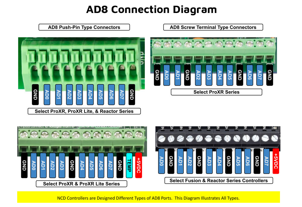
As shown in the graphic, ProXR AD8 controllers are available with multiple analog input connector options. One of the connector styles shown corresponds to the specific board you are viewing, allowing you to quickly identify how sensors will physically connect. All analog inputs share a common ground, simplifying wiring and making it easy to connect multiple sensors to a single controller.
Once connected, A/D input values can be used consistently across N-Button and Base Station software for automation, relay control, monitoring, and diagnostics. This unified approach ensures predictable behavior from hardware to software, whether you are building a simple monitoring system or a fully automated control solution.
Analog Inputs Controlling Relays
ProXR AD8 relay controllers allow analog inputs to directly control onboard relays using the same A/D input data used by N-Button and Base Station software (see Relay Activator section below). This makes it easy to monitor sensor values, automate relay behavior, and visualize input data across all supported software tools.Analog to Digital Connections
AD8 controllers are designed for stable sensor and switch monitoring. A/D inputs should never be left floating - each input must connect to a voltage or ground.A built-in 10K pull-up/pull-down resistor (jumper-selectable) ties each input to +5V or ground to prevent floating conditions. While this resistor adds slight loading, the improved stability far outweighs any minor interference.
AD8 Command Set
The AD8 Command Set reads analog voltages using the controller's 8-channel 8/10-bit ADC.- 8-bit mode: Converts 0 - 5V to values from 0 to 255
- 10-bit mode: Converts 0 - 5V to values from 0 to 1023
What a Command Looks Like
At its simplest, an AD8 command is only two bytes:254 150 - Read Input 1
0xFE 0x96 - If you require Hex
The controller processes the command and returns a value byte Decimal: 0-255, Hex: 0x00-0xFF when the operation completes. For the complete list of commands, download the AD Quick Start Guide.
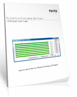
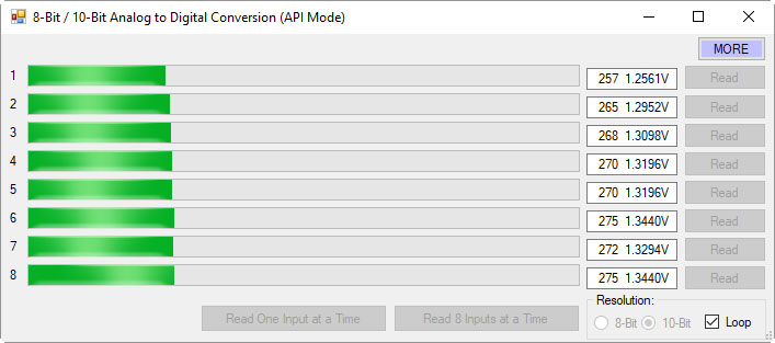
View A/D Input Data in Real Time
Base Station software allows you to read all analog inputs in real time while clearly displaying the exact command data being sent to and from the controller. In the example shown, all eight A/D input channels are read simultaneously and displayed as live numeric values along with a real-time graph, making it easy to visualize how each input changes over time.
Because Base Station shows the actual commands used to read the A/D inputs, it becomes an invaluable learning and diagnostic tool. You can see precisely how input values are requested, returned, and interpreted by the controller, then copy those commands directly into your own applications or custom software. This dramatically simplifies development, testing, and troubleshooting when integrating A/D inputs into larger systems.
Whether you are validating sensor behavior, monitoring multiple inputs at once, or building your own custom control software, Base Station gives you clear visibility into both the data and the communication behind it.
💡 Relay Pros ProTip:
Base Station can show you the exact command used to read the analog inputs. Click the More button in the upper-right corner of the Base Station window to expand the interface and display the command data being sent to and from the controller.
As you read inputs or monitor channels in real time, the software displays the precise commands used to request the A/D values and the data returned by the controller. This makes Base Station an excellent learning tool for developers - you can watch the commands being generated and then use the same decimal or hexadecimal values directly in your own software.
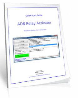
AD8 Relay Activator
Control relays with a switch or button connected directly to the board for manual control. For full details download the AD8 Relay Activator Quick Start Guide.
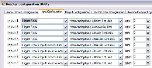
Relay Activator
Relay Activator and Analog Inputs
Base Station Software's Relay Activator is ideal for applications that primarily rely on computer control but still require occasional manual operation. By connecting external buttons or switches, you can take direct, hands-on control of any relay without giving up software-based control.This creates true bi-directional control. For example, a relay can be turned ON through the computer interface and later turned OFF using a physical switch - or vice versa. Whether you're testing, troubleshooting, or building a hybrid manual/software-controlled system, Relay Activator keeps everything synchronized and predictable.
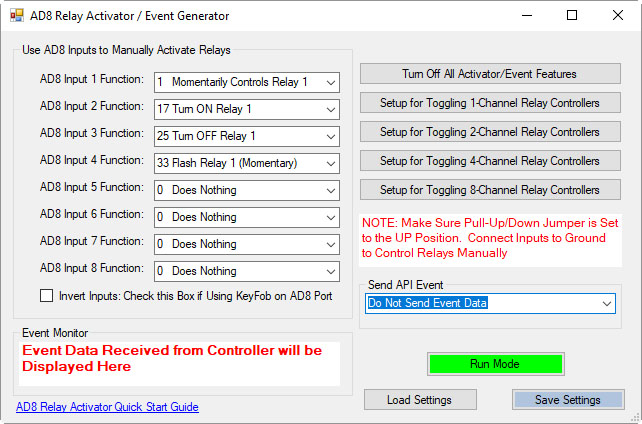 As shown in the example, each input includes a pull-down menu that allows you to select exactly how that input will control a relay. This makes configuration fast and intuitive - simply choose the desired action for each input without writing any code.
Each of the 8 input channels can be configured to control relays 1 through 8, with multiple action types available. This flexibility allows every input to perform exactly the function your application requires.
This level of control makes Relay Activator perfect for operator panels, test benches, safety overrides, and any application where manual interaction and software automation need to work together seamlessly.
AD8 Relay Activator Quick Start Guide.
Available Relay Actions per Input
Each input can be assigned one of the following actions:
- Momentary Control - Activates the relay only while the input is engaged
- Toggle Relay State - Alternates the relay between ON and OFF
- Turn Relay ON - Forces the relay into the ON state
- Turn Relay OFF - Forces the relay into the OFF state
- Flash Relay (Momentary) - Pulses the relay while the input is active
- Flash Relay (Toggle) - Toggles flashing behavior ON and OFF
💡 Relay Pros ProTip
Use the Turn Relay OFF action as a panic-stop or fail-safe control. A single button, switch, or sensor input can immediately force one relay - or multiple relays - into the OFF state. This is ideal for emergency stops on machinery, instantly disabling door locks, or overriding automation logic when a quick shutdown is required.AD8 with N-Button
Using N-Button software, you can control relays, build desktop meters that show real-time readings from the AD8 inputs. You can also create automatic push notifications messages triggered by those sensor values.
N-Button Software
Using A/D Inputs with N-Button
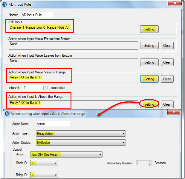
N-Button Lite and Pro support powerful A/D Input Automation rules that allow you to automatically control relays based on analog input levels. Simply define a voltage threshold or range, and N-Button will energize or de-energize relays as conditions change.N-Button also supports Send Email and Text Message actions (Push Notifications), enabling automatic alerts when an A/D input reaches a specific level or falls within a defined range. Relay control and notifications can work together seamlessly, all driven by live A/D input data.
Works Seamlessly with N-Button Software
- Build desktop meters that show real-time sensor data
- Create dashboards with multiple sensor feeds
- Trigger Push Notification alerts from A/D thresholds
- Control relays based on sensor conditions - no programming required
Using the Input Information
 N-Button allows you to use A/D input values in multiple ways without writing code. Numeric values or value ranges can be used to:
- Trigger text or email alerts when thresholds are exceeded
- Control individual relays or banks of relays
- Display live readings on customizable desktop meters
Control Relays with A/D Inputs
N-Button Lite/Pro software makes it incredibly easy to automate relay control using A/D input levels from this board. Simply create an Automation rule that links any A/D input channel to any relay channel. When the input voltage reaches the threshold you define, the relay energizes (turns on). When the input drops below that threshold, the relay de-energizes (turns off). No programming required.Precision + Performance
High-resolution readings ensure accurate measurements, even in demanding environments. Stream live data or automate actions based on your input thresholds.Create Desktop Meters
Each meter can be individually labeled, like the "Soil Moisture" label shown, making it easy to identify each sensor at a glance. Meter increments are fully customizable - the "Customizable Increments" callout shows how you can adjust the scale to match your application, whether you need fine-grained precision or a broader overview.
N-Button also allows you to arrange multiple meters on your desktop, creating a personalized dashboard that updates in real time. This makes it simple to compare different sensors side by side, spot trends, and react quickly if readings go outside expected ranges (unless you have the relays set automatically). Whether you're monitoring a single sensor or a full set of eight, N-Button makes live data monitoring intuitive and actionable.
Push Notification
N-Button software also includes a powerful point-and-click messaging system that sends alerts to the recipients you choose. Because N-Button runs on your PC, it can automatically deliver text messages and/or emails directly from your computer.Send SMS and email alerts when voltage levels are reached. Customize the subject and message to identify exactly what triggered the alert. You can even set repeat notifications at a defined interval until the input level returns to normal.
Visit our N-Button Page
Scales from Simple to Full Automation
N-Button Lite turns your PC into a powerful relay and sensor control system - no programming required. Create desktop buttons, live meters, and automation rules that control relays, monitor A/D inputs, and send alerts in real time. It's point-and-click control that scales from simple manual operation to full automation across multiple boards.
N-Button Lite - Full Relay Control
Relay Software
N-Button Lite is third-party software (sold separately) that gives you full relay control and real-time A/D input monitoring without writing a single line of code. It may look simple at first glance, but don't let that fool you - this is a surprisingly powerful tool with a wide range of real-world applications.Create desktop buttons and meters, monitor live input values, and control relays instantly - all from an intuitive point-and-click interface.
Create Buttons & Widgets
 N-Button Lite/Pro lets you build floating desktop widgets that can:
- Control relays and read inputss
- Create buttons to control relays
- Read A/D inputs
- Create live meters from inputs
- Launch applications
N-Button also includes special widgets designed specifically for the boards on this site.
💡 Relay ProTip:
Start with simple manual buttons in N-Button Lite, then layer in automation rules once you're comfortable. You don't have to build everything at once.
Supports Up To 16 Widgets
N-Button Lite offers the same widget types as the Pro version but is limited to 16 total widgets - perfect for smaller setups or budget-friendly applications.Need more? You can upgrade to N-Button Pro at any time.
USB and Network Compatible
N-Button Lite works over Serial/USB or Network connections between your computer and the relay board. Add or modify widgets easily using N-Button Lite Manager to create the exact look and behavior you want. N-Button Lite supports this relay board and any ProXR Relay board with up to 16-widgets.Control Multiple Boards
N-Button Lite software can control multiple devices connected to the same computer or network, allowing you to manage relays, inputs, meters, and automation across several boards from a single interface. Use the built-in Device Manager to easily add, remove, or modify boards and maintain a clear list of all connected devices. Each device is handled independently, making it easy to build scalable systems without adding complexity.For example, a single PC can monitor A/D inputs on one board while controlling relays on multiple network-connected boards.
Relay Control with N-Button
Create buttons on your computer's desktop that can control relys and show their status in real time. Buttons can be configured to control each relay on the board.
Relay Control
Create Relay Buttons
Relay Button Widgets are the heart of N-Button. They let you turn relays ON or OFF instantly from your desktop - no programming, no scripting, and no setup headaches. Using an intuitive point-and-click interface, you can create exactly the type of control you need in seconds.Create:
- A simple ON button
- A simple OFF button A toggle button (one click ON, next click OFF)
 |
 |
 |
 |
Create Buttons That Show Status
Relay Status Widgets automatically reflect the live state of each relay. As shown in the example, buttons can change color based on whether a relay is ON or OFF, so a quick glance at your screen tells you exactly what's happening in real time.This visual feedback reduces guesswork and makes it easy to monitor multiple relays at once - especially in systems where knowing the current state is just as important as controlling it.
Create Custom Buttons
Custom Buttons give advanced users access to the full power of the ProXR Command Set, one of the most advanced relay command systems in the industry. With N-Button Lite, you can send any supported ProXR command with a single button press - all without needing to write or compile code.Each button can be fully customized to match your workflow. Change the button color, shape, and label, and configure colors to automatically update based on relay status. In the example shown, different colors clearly indicate ON and OFF states, making relay control both intuitive and visually unmistakable.
Whether you need simple control, live status feedback, or advanced command execution, N-Button buttons give you fast, flexible, and reliable control right from your desktop.
AD8 with N-Button
Using N-Button software, you can control relays, build desktop meters that show real-time readings from the AD8 inputs. You can also create automatic push notifications messages triggered by those sensor values.
Using A/D Inputs with N-Button
A/D Inputs
All ProXR Lite boards and ProXR boards that begin with ZADR or ZADSR include an onboard 8-channel Analog-to-Digital converter in addition to relay control. Each channel accepts a 0-5V DC input and converts it into a numeric value for processing.Using the AD8 Command Set, analog voltages are translated into digital values (8- or 10-bit resolution, depending on configuration), making it easy to monitor and act on sensor data from a wide range of devices.
Control Relays Based on Analog Input Levels
N-Button Lite and Pro support powerful A/D Input Automation rules that allow you to automatically control relays based on analog input levels. Simply define a voltage threshold or range, and N-Button will energize or de-energize relays as conditions change.N-Button also supports Send Email and Text Message actions (Push Notifications), enabling automatic alerts when an A/D input reaches a specific level or falls within a defined range. Relay control and notifications can work together seamlessly, all driven by live A/D input data.
Works Seamlessly with N-Button Software
Each A/D channel supports industry-standard 0-5V inputs, making it simple to integrate a wide range of sensors without extra hardware. Using N-Button, you can:- Build desktop meters that show real-time sensor data
- Create dashboards with multiple sensor feeds
- Trigger Push Notification alerts from A/D thresholds
- Control relays based on sensor conditions - no programming required
Using the Input Information
N-Button allows you to use A/D input values in multiple ways without writing code. Numeric values or value ranges can be used to:- Trigger text or email alerts when thresholds are exceeded
- Control individual relays or banks of relays
- Display live readings on customizable desktop meters
Control Relays with A/D Inputs
N-Button Lite/Pro software makes it incredibly easy to automate relay control using A/D input levels from this board. Simply create an Automation rule that links any A/D input channel to any relay channel. When the input voltage reaches the threshold you define, the relay energizes (turns on). When the input drops below that threshold, the relay de-energizes (turns off). No programming required.Precision + Performance
High-resolution readings ensure accurate measurements, even in demanding environments. Stream live data or automate actions based on your input thresholds.Create Desktop Meters
Each meter can be individually labeled, like the "Soil Moisture" label shown, making it easy to identify each sensor at a glance. Meter increments are fully customizable - the "Customizable Increments" callout shows how you can adjust the scale to match your application, whether you need fine-grained precision or a broader overview.
N-Button also allows you to arrange multiple meters on your desktop, creating a personalized dashboard that updates in real time. This makes it simple to compare different sensors side by side, spot trends, and react quickly if readings go outside expected ranges (unless you have the relays set automatically). Whether you're monitoring a single sensor or a full set of eight, N-Button makes live data monitoring intuitive and actionable.
Push Notification
N-Button software also includes a powerful point-and-click messaging system that sends alerts to the recipients you choose. Because N-Button runs on your PC, it can automatically deliver text messages and/or emails directly from your computer.Send SMS and email alerts when voltage levels are reached. Customize the subject and message to identify exactly what triggered the alert. You can even set repeat notifications at a defined interval until the input level returns to normal.
Control More Than Just Relay Boards
 Your widgets aren't limited to relay boards. You can configure buttons to:
- Send custom serial/IP data
- Open files, folders, or programs
- Launch applications
- Send HTTP requests
- Trigger data lists
N-Button Videos
Plan Your Power with Confidence
Get reliable performance every time! Use these real-world specs to build accurate power budgets, protect your board, and ensure every relay and module runs smoothly under any conditions.
Power & More
"Reliable Power = Reliable Switching"
Board Performance Ratings
This tab brings together the essential performance ratings you'll want to know for NCD SPDT Relay Controllers and their supported communication modules. You'll find practical electrical requirements, power consumption estimates, operating limits, relay timing details, and more-all based on typical 12VDC operation at 70°F (21°C). Think of it as a reliable snapshot of how our hardware behaves under real-world conditions. Because every installation is unique, some values are estimates and may evolve as designs and testing continue. Use this information as a planning tool to help you choose the right controller, build an accurate power budget, and understand the capabilities built into every NCD SPDT relay board.Powering from a Battery or Solar Panel?
NCD relay controllers are well-suited for battery-powered and solar-charged applications when operated within the recommended 10 - 15VDC range. This makes them ideal for remote, mobile, and off-grid installations using common 12V battery systems with solar charging. The power consumption data on this page helps you estimate runtime, size your battery, and avoid over-discharge. Staying within the voltage limits ensures stable, reliable operation in long-term battery and solar-powered setups.💡 Relay ProTip:
When powering a controller from a battery or solar power, keep voltage between 10-15VDC for reliable operation. Falling outside this range can cause unstable behavior or unexpected resets.
The SPDT Relay
SPDT (Single Pole Double Throw) relays include three terminals: Common (COM), Normally Open (NO), and Normally Closed (NC)
- When the relay is off, COM is connected to NC.
- When the relay is energized, COM switches to NO.
2 Million+ Cycles
ProXR relays are built for longevity - expect years of reliable operation. The SPDT relay is rated for millions of mechanical cycles. Every board ships with a 5-year warranty and 30-day money-back guarantee.SPDT Relay Board
SPDT Relay Controller Specifications
This table outlines key performance ratings for all NCD SPDT Relay Controllers, based on 12VDC operation at 70°F (21°C). Many values are estimated and may be updated over time. Some ratings reflect standard, out-of-the-box settings without performance optimizations applied.Processing times can vary depending on background services and the commands you use. Standby power values assume no communication module is installed and no relays are active. For a more accurate power estimate, be sure to include the consumption of any installed communications module and any energized relays.
| Specs of NCD SPDT Relay Boards | Minimum | Nominal | Maximum | Notes |
| Operational Voltages | 10VDC | 12VDC | 15VDC | |
| Standby Power Consumption | 35mA | 100mA | 200mA | No Active Relays, No Com Module |
| Relay Power Consumption | 28mA | 35mA | 60mA | Consumption of Each Activated Relay |
| Operational Temperature Range | -40°F (-40°C) | 70°F (21°C) | 185°F (85°C) | Theoretical Component Limits Shown |
| Storage Temperature Range | -67°F (-55°C) | 70°F (21°C) | 185°F (85°C) |
Theoretical Component Limits Shown |
| Operational Ambient Air Humidity | 0% | 50% | 70% | Non-Condensing Humidity Values Shown |
| Relay Activation Time | 4ms | 5ms | 10ms | Needs Further Validation |
| Relay Deactivation Time | 5mS | 10mS | 15mS | Needs Further Validation |
Communication Modules
Communication Module Specifications
This table provides a quick, clear overview of all NCD Communication Modules. While each module operates at 3.3VDC, the values shown here reflect the impact on a 12VDC master controller at 70°F (21°C). Use the maximum ratings for power-budget planning - they represent short-term peak consumption and may include estimated values that are updated as modules evolve.| Specs of NCD Communication Modules | Minimum | Nominal | Maximum | Notes |
| Operational Temperature Range | -40°F (-40°C) | 70°F (21°C) | 185°F (85°C) | Theoretical Component Limits Shown |
| Storage Temperature Range | -67°F (-55°C) | 70°F (21°C) | 185°F (85°C) | Theoretical Component Limits Shown |
| Operational Ambient Air Humidity | 0% | 50% | 70% | Non-Condensing Humidity Values Shown |
| USB Module Power Consumption | N/A | N/A | N/A |
USB Modules are Powered by the USB Port Do Not Consume Device Current |
| RS-232 Module Power Consumption | 10mA | 20mA |
|
|
| Ethernet Module Power Consumption | 58mA | 82mA | 100mA | |
| WiFi Bluetooth USB Module Power Consumption | 37mA | 50mA | 100mA | Up to 300 Foot Indoor Wireless Range, Unobstructed. Up to 50 Foot Range Through Walls |
| 900MHz Wireless Module Power Consumption | 13mA | 30mA | 50mA | Up to 1,000 Foot Indoor Wireless Range, up to 2 Mile Outdoor Wireless Range using Included Antennas. Up to 28 Miles Outdoor Wireless Range using High-Gain Antennas. |
| KFX Wireless Key Fob | 11mA | 15mA | 25mA | Up to 200 Feet Outdoor Wireless Range using 1, 2, 3, 4, or 5 Button Key Fobs. Up to 700 Feet Outdoor Wireless Range using 8-Button Remotes |
A/D Inputs
AD8 Analog Input Usage Notice
Analog inputs should never have voltage applied when the controller is powered down. If your application requires voltage to remain on an input, add a 220-ohm current-limiting resistor to each channel to protect the controller from damage. Keep all analog inputs within the 0 - 5VDC range - exceeding this limit can permanently damage the on-board CPU. Most inputs include a 10K pull-up or pull-down resistor to keep the line stable when unused, but note that this resistor may introduce a slight bias in readings for certain sensors.Accessories
Power Supply
 The PWR12 is regulated power supply providing clean power necessary for
the performance of these boards. The PWR12 US power supply is a 120VAC to 12VDC 1.25A 60Hz regulated
power supply and it plugs into the barrel connector on the board. The output connector is a 2.1mm I.D. x 5.5mm
O.D. x 9.5mm R/A barrel connector.
The PWR12 is regulated power supply providing clean power necessary for
the performance of these boards. The PWR12 US power supply is a 120VAC to 12VDC 1.25A 60Hz regulated
power supply and it plugs into the barrel connector on the board. The output connector is a 2.1mm I.D. x 5.5mm
O.D. x 9.5mm R/A barrel connector.
Click Here for More
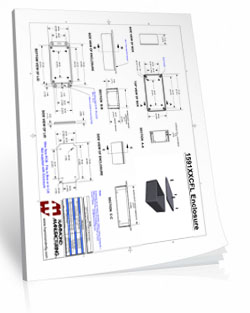
Enclosure
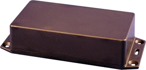 The CFL Enclosure is an undrilled, non-waterproof enclosure and is available at checkout for this controller.
Spec Sheet: CFL Spec Sheet
CAD Drawing: CFL CAD Drawing
3D Model: CFL_3D
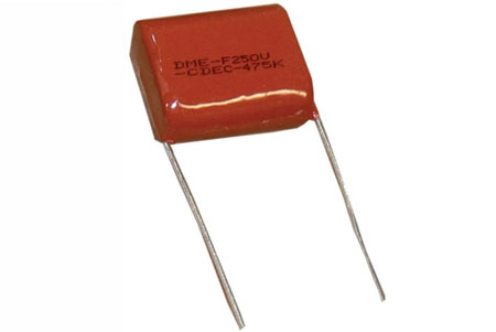
Induction Suppression
Controlling
an inductive load using our relay controllers requires the use of induction suppression capacitors. The purpose of this capacitor
is to absorb the high voltages generated by inductive loads, blocking them from the contacts of the relay. Without this capacitor,
the lifespan of the relay will be greatly reduced. Induction can be so severe that it electrically interferes with the microprocessor
logic of our controllers, causing relay banks to shut themselves down unexpectedly.
Click Here for More
N-Button Lite
N-Button
Lite software allows you to create buttons to control relays and show the status without programming. Create buttons to quickly control
the relay. Create meters for reading
the variable input sensors connected to the AD inputs of this board in real time! Enter the COM ports of the board and you are communicating
through the USB port the board is plugged into!
Click Here for More
Relay Timer R1X
 Relay Timer
Software allows you control the relay from a time schedule you create! The software can be installed on a PC and uses the
computers clock for an accurate time control. Enter the board's COM port and the software will communicate
through the USB port the board is plugged into. Look for Relay Timer R1X during checkout.
Click Here for More
Relay Timer
Software allows you control the relay from a time schedule you create! The software can be installed on a PC and uses the
computers clock for an accurate time control. Enter the board's COM port and the software will communicate
through the USB port the board is plugged into. Look for Relay Timer R1X during checkout.
Click Here for More
Relay Wiring Made Simple
From simple on/off switching to advanced AND/OR logic, these examples show exactly how to connect your relays for real-world applications. Learn the tricks to control lights, motors, sensors, and more with confidence.
Get a printout of this page
Relay Logic
"Using a light as an example load, let's wire to the board"
Relay Wiring Samples
This page provides simple examples showing how to wire a single relay - or multiple relays - for common switching applications. We use a light as the example load, but you can substitute a gate controller, security panel input, dry contact device, motor trigger, or most other switched loads. These wiring samples demonstrate different ways to connect relays to achieve the switching behavior you need.Relay Types
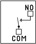
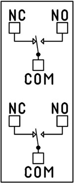
SPDT Relay
SPDT (Single Pole Double Throw) relays include three terminals: Common (COM), Normally Open (NO), and Normally Closed (NC).
- When the relay is off, COM is connected to NC.
- When the relay is energized, COM switches to NO.
Your load can be wired to either the NO or NC terminal depending on whether you want the device to turn on when the relay activates or when it releases. Examples below demonstrate both wiring methods. The SPDT relays offered on this site are 5-Amp, 10-Amp and 20-Amp models.
SPST Relay
SPST (Single Pole Single Throw) relays provide two terminals: Common (COM) and Normally Open (NO).
When the relay coil is energized, COM connects to NO to power the load. The only SPST relays offered on this site are our 30-Amp models. All SPDT examples shown on this page apply to these relays as long as the example does not require a Normally Closed terminal.
DPDT Relay
A DPDT (Double Pole Double Throw) relay contains two SPDT switches that operate together.
- Each side includes its own COM, NO, and NC terminals.
- Both internal switches change state at the same time.
This allows you to control two independent circuits with one relay. Wiring for each side of a DPDT relay follows the same rules as an SPDT relay, so the examples on this page apply directly. We offer the DPDT relays in 1-Amp, 3-Amp and 5-Amp models on ProXR boards starting at 8 relays.
Relay Grouping
Relay Grouping in the ProXR Command Set lets you combine individual relays to function like a DPDT relay using separate channels. This is ideal when you need to control multiple relays simultaneously or exceed the 5-Amp switching limit of our standard DPDT relays.Relay Logic Examples
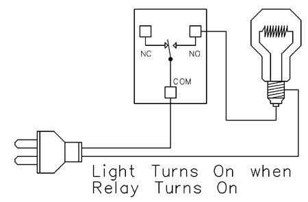
Example 1 - Simple Off/On Control
This example shows the most basic way to use a relay to switch a device such as a light. When the relay energizes, its NO (Normally Open) contact closes to COM (Common), completing the circuit and turning the light on.Only a single power wire is switched in this setup, making it the simplest method for controlling a light - or any device - using a relay.
Use this example for switching a light or any device you want to power only when the relay is on.
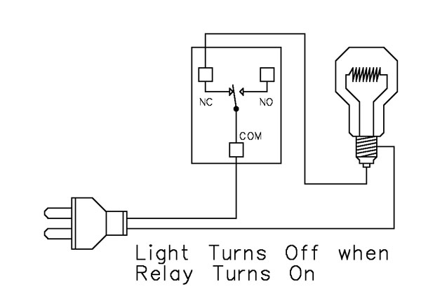
Example 2 - Simple On/Off (Using NC Contact)
This wiring method keeps the light on by default. The relay switches a single power wire through the COM (Common) and NC (Normally Closed) terminals.When the relay is not energized, the NC contact is closed to COM and the light remains on.
When the relay energizes, the NC contact opens, interrupting power and turning the light off.
This approach is ideal for devices that stay on most of the time, reducing relay wear since it doesn't need to remain energized to keep the device powered. It's also a useful method for power-cycling equipment - energizing the relay momentarily will turn the device off.
💡 Relay Pros ProTip:
For devices that stay on most of the time, use the NC contact. This reduces relay wear and extends the life of both the relay and your power supply.
Example 3 - AND Logic Using Two Relays
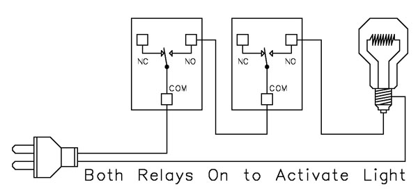 This example shows how two relays can work together so a light turns on only when both relays are energized. This creates an AND Logic condition:
Relay 1 AND Relay 2 must be on for the light to receive power.
A single power wire is switched, but it must pass through both relay contacts before reaching the light. This setup is ideal when two conditions must be met at the same time - such as requiring input from multiple sensors or system parameters.
MirC/MirX/MirM Users:
This wiring requires two contact closure inputs on the sender board before the receiver's relay activates. Use this approach when two independent outputs must close before turning on the light.For example, a light could turn on only when:
1. A light sensor detects it's dark AND
2. A motion sensor detects activity in the room
Example 4 - AND Logic Using Three Relays
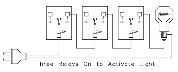 This example expands on the previous AND Logic concept. Here, the light will turn on only when all three relays are energized:
Relay 1 AND Relay 2 AND Relay 3 must be on for power to reach the light.
A single power wire is routed through all three relay contacts. Wiring from the NO (Normally Open) of Relay 1 to the COM (Common) of Relay 2, then from the NO of Relay 2 to the COM of Relay 3, creates a series path that requires every relay to energize before the light can activate.
This method can be scaled easily - just continue wiring NO of each relay to the COM of the next relay. Add as many relays as needed to meet your logic or safety requirements.
Example 5 - AND/OR Logic with Override
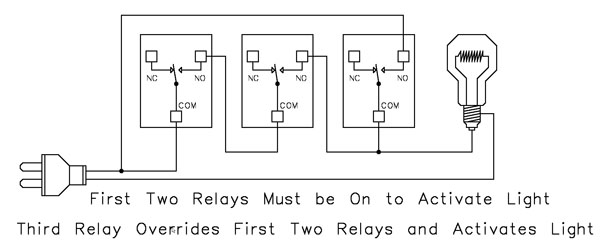 This example demonstrates a combined AND/OR logic setup. The light will turn on when:
- Relay 1 AND Relay 2 are both energized OR Relay 3 is energized (override)
- For example:
- Relay 1 = night/day sensor
- Relay 2 = motion sensor
- Relay 3 = manual override (local switch)
A/D Board Users:
The Relay Activator function on any A/D board or ProXR Lite board lets you connect a button or switch to any A/D input. This input can then control the override relay, giving you a convenient local button to manually override the first two relays.MirC/MirX/MirM Users:
Add a manual button or switch to trigger the third relay when you need direct control instead of sensor-driven control.Reactor Users:
A local button or switch can be wired to the third relay input to provide a manual override for sensor-based logic.Example 6 - OR Logic (Either Relay Activates)
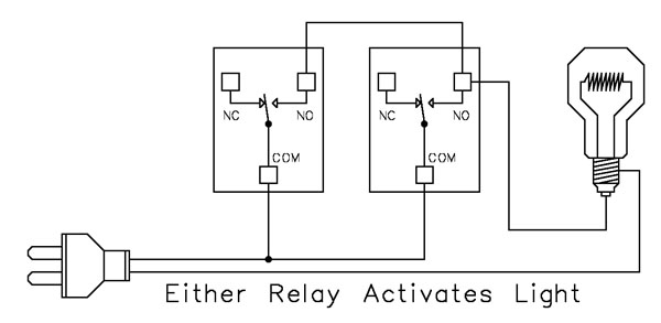 This example demonstrates OR Logic - the light will turn on when either relay is energized. Only one power wire is switched, but it can pass through Relay 1 or Relay 2 to reach the light.
- If Relay 1 activates, the light turns on
- If Relay 2 activates, the light turns on
- If both activate, the light remains on
- A timer controlling one relay, with a manual or secondary control for the other.
- Two sensors where either condition (motion detected or low light, for example) should activate the light.
A/D Board Users:
The Relay Activator function on any A/D board or ProXR Lite board lets you connect a button or switch to any A/D input. This input can then be used as a manual control of the relay.MirC/MirX/MirM Users:
Add a manual button or switch to trigger the third relay when you need direct control instead of sensor-driven control.MirC/MirX Users:
Wire two contact closure inputs into the sender board - either input can trigger the receiver relay to control the light.Example 7 - 3-Way Switch (Relay-Based 3-Way Control)
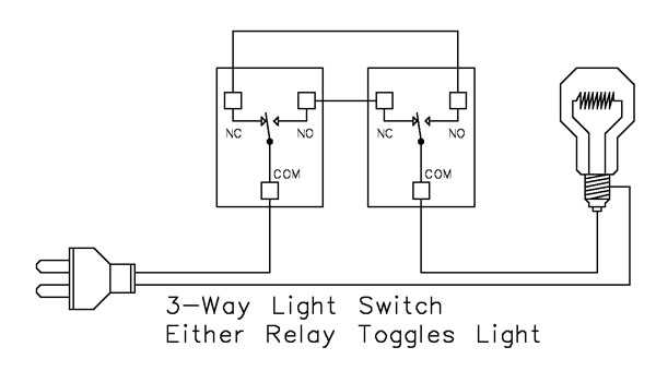 This example shows how to create a 3-way light switch setup using relays. A traditional 3-way circuit allows two switches to control the same light from different locations. In this wiring sample, each physical switch is replaced by a relay - but the operation is the same.
Only one power wire is switched, and the relays toggle the light depending on their current state.
- Activating either relay will toggle the light
- Activating both relays at the same time has the same effect as flipping both switches at once
Example 8 - DC Motor Direction Control
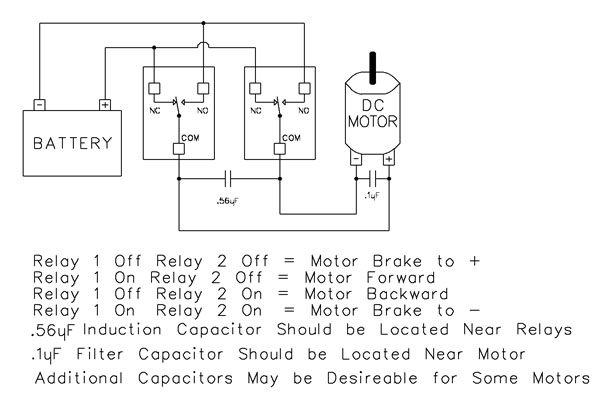 This example demonstrates how to control the direction of a DC motor using two relays. By changing how the motor's leads connect to power, you can run the motor forward, reverse, or place it in a brake state. Braking is achieved by tying both motor terminals to the same power connection, which stops rotation through Faraday's Law.
- Relay Operation Summary
- Relay 1 Off / Relay 2 Off → Motor Brake to +
- Relay 1 On / Relay 2 Off → Motor Forward
- Relay 1 Off / Relay 2 On → Motor Reverse
- Relay 1 On / Relay 2 On → Motor Brake to -
- The induction suppression capacitor prevents the relay from shutting off due to motor back-EMF
- The 0.1µF filter capacitor reduces electrical noise, especially useful when powering sensitive electronics such as radios or amplifiers.
- Capacitor Placement
- Place the induction suppression capacitor near the relays
- Place the filter capacitor near the motor
- Additional capacitors may be needed for certain motors
Motors draw significantly more current at startup than during continuous operation - often 2-3 times their rated running current. For example, a motor rated at 5A (125VAC) may require 10-15A to begin turning. Always select a relay that exceeds the motor's initial inrush current, not just its running current. In this case, a 20-30A relay provides optimal performance and longevity.
💡 Relay Pros ProTip:
Motors and inductive loads often draw 2-3x their rated current at startup. Always choose a relay that exceeds the motor's inrush current, not just its running current.
Instant Control & Diagnostics
Free Base Station software gives you full, hands-on control of your controller the moment you plug it in. It automatically identifies your board, loads the correct interface, and lets you test, control, and verify every supported feature - making setup, learning, and troubleshooting fast and frustration-free.
Base Station Software
"Every feature, every device - no other board has this kind of software"
Compatible with All Boards on this Site
Base Station is a free software download that works by talking directly to your controller to identify the model, then automatically loads the correct graphical interface for controlling and testing that device. It's a great way to learn how any NCD controller works and doubles as a powerful diagnostic tool to verify your device is operating as designed.Base Station exercises every supported feature on every supported device. For learning, testing, and troubleshooting NCD boards, this is the ultimate reference tool.
Useful Features
There are some useful features to look for when using Base Station Software to control, test, or configure your device:- Links to Quick Start Guides and documentation
- Discovery of network devices with IP address display
- Command Set Window for viewing raw commands (especially helpful for ProXR users)
- Base Station displays commands in decimal or hexadecimal formats.
- Relay Activator with Analog Inputs
Device Identification
Click the Device Identification window to view important read-only info about your controller.Watch for the field labeled "Documentation Related to this Controller" - it's a complete list of articles connected to your device. Click any entry to open it. (Internet required.)
All devices released in 2012 and later support Device Identification.
Device Command Sets
Base Station asks the controller which command sets it supports, then displays them when the software launches. Some devices show more command sets, others fewer - it's always based on the board.
ProXR users can access the entire ProXR Command Set to turn relays on/off and run every available function.
Control All ProXR Functions
Turn relays on or off, read relay status, monitor inputs - Base Station gives full ProXR control through a clean point-and-click interface.For programmers, Base Station also shows every command being sent to the board, making it a great tool for learning and development.
💡 Relay Pros Pro Tip:
Use Base Station as a Command Generator! Base Station is not only a control interface - it is also a powerful development tool. Click the More button in the upper-right corner of the window to expand the interface and display the command output being sent to the controller. As you operate relays using the point-and-click controls - including toggle commands, timers, and flashers - the software displays the exact command being transmitted.
Developers can use this feature to quickly determine the decimal or hexadecimal commands required for heir own software without manually building commands from the documentation.
AD8 Relay Activator
Control relays with a switch or button connected directly to the board for manual control. For full details download the AD8 Relay Activator Quick Start Guide.
Relay Activator
Relay Activator and Analog Inputs
Base Station Software's Relay Activator is ideal for applications that primarily rely on computer control but still require occasional manual operation. By connecting external buttons or switches, you can take direct, hands-on control of any relay without giving up software-based control.This creates true bi-directional control. For example, a relay can be turned ON through the computer interface and later turned OFF using a physical switch - or vice versa. Whether you're testing, troubleshooting, or building a hybrid manual/software-controlled system, Relay Activator keeps everything synchronized and predictable.
As shown in the example, each input includes a pull-down menu that allows you to select exactly how that input will control a relay. This makes configuration fast and intuitive - simply choose the desired action for each input without writing any code.
Each of the 8 input channels can be configured to control relays 1 through 8, with multiple action types available. This flexibility allows every input to perform exactly the function your application requires.
Available Relay Actions per Input
Each input can be assigned one of the following actions:
- Momentary Control - Activates the relay only while the input is engaged
- Toggle Relay State - Alternates the relay between ON and OFF
- Turn Relay ON - Forces the relay into the ON state
- Turn Relay OFF - Forces the relay into the OFF state
- Flash Relay (Momentary) - Pulses the relay while the input is active
- Flash Relay (Toggle) - Toggles flashing behavior ON and OFF
AD8 Relay Activator Quick Start Guide.
Reactor Users
Reactor Events Settings
All Reactor configuration is handled inside Base Station.You can define when a relay or event activates based on the voltage readings of analog inputs. Inputs can trigger relays directly or trigger timed events.
The Reactor GUI only appears when Base Station detects a Reactor board, and some functions may not display for other board types.
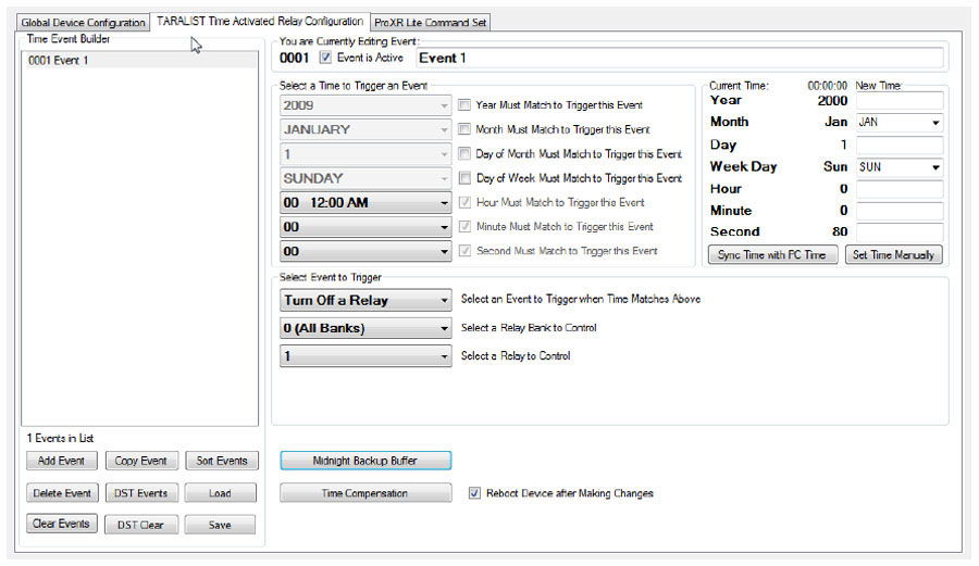
TaraList Users
TaraList Setup
Base Station includes configuration tools and scheduling upload controls for TaraList Time Activated Boards.TaraList users will see setup pages for creating and uploading time schedules. ProXR users won't - those pages appear only when Base Station detects a TaraList controller.
Software Options


 Not a programmer and these boards look intimidating? Don't worry. Powerful software tools make it easy to get connected, discover attached devices, monitor inputs in real time, and control relays without writing a single line of code. Create on-screen buttons, desktop meters, timed events, and automated actions that respond to inputs, schedules, or system conditions - all from an intuitive graphical interface.
Base Station
Base Station software supports every feature on any ProXR board - no other controller manufacturer even comes close to offering this type of software. Download Base Station.
Base Station Software
Compatible with ALL Boards on This Site
Base Station is a free software download that works by talking directly to your controller to identify the model, then automatically loads the correct graphical interface for controlling and testing that device. It's a great way to learn how any NCD controller works and doubles as a powerful diagnostic tool to verify your device is operating as designed.Base Station exercises every supported feature on every supported device. For learning, testing, and troubleshooting NCD boards, this is the ultimate reference tool.
User Interface
Base Station gives you a list of command sets supported by your controller. Just click any item once to open the custom graphical interface that was created alongside the firmware. Each command set corresponds with a module installed inside your device."
Device Identification
Click the Device Identification window to view important read-only info about your controller.Watch for the field labeled "Documentation Related to this Controller" - it's a complete list of articles connected to your device. Click any entry to open it. (Internet required.)
All devices released in 2012 and later support Device Identification.
Device Command Sets
Base Station asks the controller which command sets it supports, then displays them when the software launches. Some devices show more command sets, others fewer - it's always based on the board.
ProXR users can access the entire ProXR Command Set to turn relays on/off and run every available function.
Control All ProXR Functions
Turn relays on or off, read relay status, monitor inputs - Base Station gives full ProXR control through a clean point-and-click interface.For programmers, Base Station also shows every command being sent to the board, making it a great tool for learning and development.
Useful Features
There are some useful features to look for when using Base Station Software to control, test, or configure your device:- Links to Quick Start Guides and documentation
- Discovery of network devices with IP address display
- Command Set Window for viewing raw commands (especially helpful for ProXR users)
- Relay Activator with Analog Inputs
Configure Buttons
N-Button Lite lets you create on-screen buttons to control relays and view their status - no programming needed. You can also build real-time meters to monitor variable input sensors connected to your board.
N-Button Lite - Full Relay Control
Relay Software
N-Button Lite is third-party software (sold separately) that gives you full relay control and real-time A/D input monitoring without writing a single line of code. It may look simple at first glance, but don't let that fool you - this is a surprisingly powerful tool with a wide range of real-world applications.Create desktop buttons and meters, monitor live input values, and control relays instantly - all from an intuitive point-and-click interface.
Create Buttons & Widgets
N-Button Lite/Pro lets you build floating desktop widgets that can:
- Control relays and read inputss
- Create buttons to control relays
- Read A/D inputs
- Create live meters from inputs
- Launch applications
N-Button also includes special widgets designed specifically for the boards on this site.
Lite vs. Pro
N-Button Lite includes the same buttons and widgets as the Pro version, but is limited to 16 total widgets. It's ideal for maller projects or cost-conscious applications where you still want full functionality. If your project grows, N-Button Pro removes the limit and supports up to 255 widgets.USB and Network Compatible
N-Button Lite works over Serial/USB or Network connections between your computer and the relay board. Add or modify widgets easily using N-Button Lite Manager to create the exact look and behavior you want. N-Button Lite supports this relay board and any ProXR Relay board with up to 16-widgets.Control Multiple Boards
N-Button Lite software can control multiple devices connected to the same computer or network, allowing you to manage relays, inputs, meters, and automation across several boards from a single interface. Use the built-in Device Manager to easily add, remove, or modify boards and maintain a clear list of all connected devices. Each device is handled independently, making it easy to build scalable systems without adding complexity.For example, a single PC can monitor A/D inputs on one board while controlling relays on multiple network-connected boards.
Time Control Software
 We offer two timer software options to support different types of automation needs: Relay Timer and Quick Timer. Relay Timer is designed for time-of-day scheduling, allowing relays to turn on and off automatically based on the computer's clock - ideal for daily routines and long-term automation. Quick Timer focuses on duration-based control, running relay sequences for a defined length of time that you manually start, making it well suited for test cycles, timed processes, and repeatable sequences.
 Choose the timer that best matches whether your application depends on when an action occurs or how long it runs.
Time Schedule Relay Control
Relay Timer software makes it easy to turn relays on and off automatically at times you choose. Create repeating schedules - daily, weekly, monthly, or on specific days - and connect using USB, serial, or your network.
Relay Timer
Time Schedule Control
Relay Timer is third-party software (sold separately) that works with all ProXR and ProXR Lite relay controllers and supports every available interface - USB, wired, wireless, and network. No matter how your board is connected, Relay Timer communicates seamlessly to deliver reliable, scheduled relay control.Precision Scheduling Using Your Computer's Clock
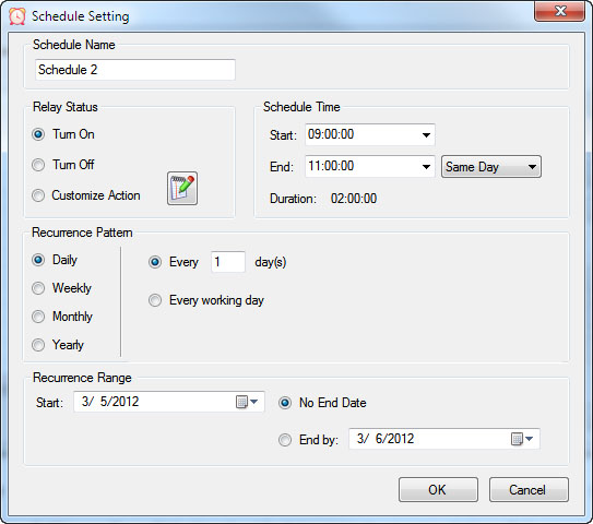 Relay Timer uses the computer's system clock to maintain accurate, drift-free timing. This ensures relay actions stay perfectly synchronized with other applications running on the same machine, such as time clocks or automation software.
A high-resolution timing engine - similar to those used in multimedia applications - provides timing accuracy down to 5 - 10 milliseconds, making Relay Timer well suited for real-time and precision-based control tasks.
High-Speed, Multi-Relay Control
Relay Timer can update up to eight relays simultaneously using the ProXR and ProXR Lite communication protocol. When speed matters, all eight relays can be updated in approximately 30 milliseconds.In multi-relay applications, Relay Timer calculates the state of all relays together, even though each relay operates independently. This ensures fast, coordinated, and predictable behavior across complex schedules.
Take Manual Control
At any time, you can manually take control of a relay to interrupt the active schedule. Resume automatic operation instantly or set a specific time for the software to return to scheduled control - ideal for maintenance, testing, or temporary overrides such as school bells for assemblies.Duration-Based Relay Control
QuickTimer lets you turn relays on or off for a set amount of time - just like setting a timer on an oven or microwave. Once the timer starts, the software handles everything automatically.
Quick Timer
Compatible with ProXR & ProXR Lite Boards
Quick Timer is third-party software (sold separately) that works with all ProXR and ProXR Lite relay controllers and supports every available interface, including USB, wired, wireless, and network connections. The software automatically communicates with your board regardless of how it's connected, making setup quick and straightforward. Designed for responsive, duration-based control, Quick Timer delivers fast, reliable relay operation for timed sequences, test cycles, and repeatable automation tasks.Duration-Based Relay Control (Not Time-of-Day Scheduling)
Quick Timer is designed for applications where how long a relay is energized matters more than what time of day it activates. Instead of using the computer's clock, Quick Timer runs sequences based on a defined time duration.
A sequence is manually started and can:
- Run once and stop automatically, or
- Loop continuously until manually stopped
Flexible Time Sequences Within a Single Duration
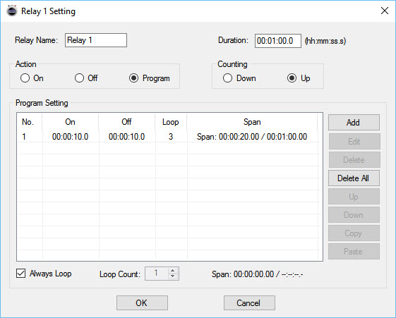 Quick Timer allows you to define a total run duration first. Within that duration, each relay can follow its own independent on/off timing pattern.
Example: 30-Second Sequence
- Relay 1 turns on for 5 seconds, then off for 5 seconds
- Relay 2 turns off for 5 seconds, then on for 5 seconds
- Relay 3 turns on for the first 10 seconds, then off for 20 seconds
- Relay 4 remains off for 10 seconds, then turns on for 20 seconds
Independent Control Per Relay
Each relay can be configured with its own timing behavior while remaining synchronized within the overall sequence duration. This allows complex, coordinated relay patterns without requiring scripting or programming.Manual Override at Any Time
Manual control is always available. Interrupt the active sequence to toggle any relay as needed, then return to automatic operation immediately or at a user-defined time.Built for Real-World Reliability
Quick Timer is designed to handle real-world operating conditions, including communication interruptions, power loss, and system instability. Rather than assuming perfect conditions, the software focuses on predictable behavior and clear user control when issues occur.Confirm Relay Timing in Seconds
Why wait hours - or days - to see if your automation works? Time Travel lets you fast-forward your computer's clock to instantly test Relay Timer schedules and Quick Timer sequences. Jump ahead in time, watch relays trigger exactly when they should, fix issues fast, and get your setup right the first time - no DeLorean required.
Time Travel
Fast-Forward Time for Testing & Automation
Time Travel software answers the age-old question of time travel - at least for your PC. This free utility lets you override and accelerate your computer's clock, making it easy to test time-based automation without waiting in real time. Time Travel is included with Relay Timer, Quick Timer, and N-Button software and is also available as a free standalone download.Instead of waiting hours or days to verify schedules, you can fast-forward time and confirm relay behavior in seconds - saving time, frustration, and repeated test cycles.
Make Time Run Faster
Time Travel can temporarily override your computer's system clock and adjust how fast time runs. Increase the clock speed to simulate long periods instantly - for example, at 3600x speed, a full day passes in just 24 seconds.This makes it easy to validate schedules, sequences, and automation logic without waiting for real-world time to pass.
Ideal for Bench Testing & Development
Time Travel is especially useful for testing any software that relies on the computer's clock, including:
- Relay Timer
- Quick Timer
- N-Button
- Other scheduling or automation applications
Presets & Automatic Time Recovery
Time Travel includes preset configurations that allow you to load saved time and speed settings quickly. Users can create, save, and export presets for future use, and the software remembers the last configuration when restarted.To protect your system, Time Travel automatically restores the computer's clock to the correct local time when the program exits. The system time is only affected while the software is running.
Simple to Use
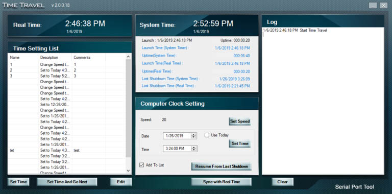 Using ime Travel is straightforward:
- Download and unzip the software
- Run TimeTravel.exe as Administrator
- Current Running Speed - Adjusts how fast the computer clock runs
- Set Time - Changes the computer clock to a specific date and time
- Resume From Last Shutdown Time - Restarts from the last simulated computer time if the system shut down unexpectedly
- Sync with Real Time - Returns the clock to real-time operation (when speed is set to 1x)
Component Library
Visual Studio Samples
 The NCD Component Library is a plug-in for the Visual Studio 2005/2008 that greatly simplifies the communications to the NCD product line. The samples can be run in Visual Studio and fully customizable to your needs. Over 40 fully functional fully working samples are included in this free download.
 Visit our Component Library Page to view all the samples available.
Protect Against Inductive Spikes
Motors, solenoids, contactors and other inductive loads can generate voltage spikes every time they switch on. For just a few dollars, suppression capacitors can help protect relay contacts and extend the life of your control system.
Simple to install and highly recommended for inductive loads, capacitors are one of the easiest ways to improve long-term system reliability.
Induction Suppression
Handling Inductive Loads (Why It Matters)
Inductive loads are anything with a magnetic coil - motors, solenoids, transformers, mag locks, door strikes, etc. These devices generate dangerous voltage spikes when switched on and off.Those spikes can:
- Destroy relay contacts prematurely
- Cause unexpected controller resets
- Knock USB devices offline
- Damage the board's power regulation circuitry
💡 Relay Pros ProTip:
Many customers skip suppression because it seems complicated. In reality, adding a suppression capacitor typically requires only two connection points and can dramatically reduce relay contact wear when switching motors, solenoids and contactors.Why You Need a Capacitor
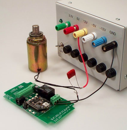 Every time an inductive device switches on, it releases a burst of high-voltage energy.
A suppression capacitor:
- Absorbs these spikes before they reach your relay
- Protects relay contacts from arcing
- Prevents interference with the microcontroller logic
- Helps maintain stable USB or serial communication
Resistive Loads Don't Need Suppression
If you're switching a purely resistive device, such as:- Incandescent/LED lighting
- Heating elements without fans
- Basic resistive appliances
- Using Relay as Dry Contact Output
Choosing the Right Capacitor
 It's simple:
Choose a capacitor with a voltage rating equal to or higher than the voltage of the device you're switching.
Example:
- Switching a 120VAC motor → Use a capacitor rated for 120VAC or higher
- Switching a 24VDC solenoid → Use a capacitor rated for 24VDC or higher
Suppression capacitors can retain a charge for a short period after power is removed. Always discharge capacitors safely before handling.
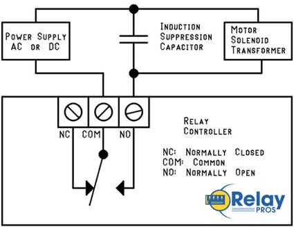
Easy Installation
Installing a suppression capacitor is straightforward:- Mount it as close to the relay as possible
- Connect it in parallel with the inductive load
- Polarity doesn't matter - capacitors used for suppression are not polarized
- Works with both AC and DC loads
Don't Share Power Supplies with Inductive Loads
Your controller must be powered by a clean, regulated power supply.Do not share the same power supply with:
- DC motors
- High-power solenoids
- Any heavy inductive device
The only exception: battery-powered systems (like automotive) where the battery naturally absorbs induction spikes.
Important Note for USB Users
USB is extremely sensitive to electrical noise. An inductive spike can cause the PC's motherboard to drop the USB port entirely.That means:
- Your controller disappears from the OS
- Your application loses communication
- You must unplug and reconnect the board