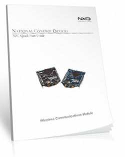
Wireless Relay 16-Channel 30-Amp with UXP Port
ZUXPR1630PROXR_XSC
Wireless Relay
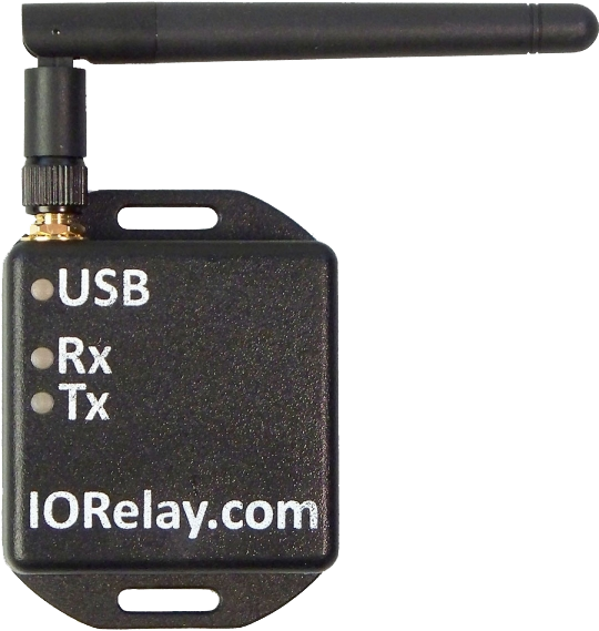
The ZADR1630ProXR_XSC Wireless Relay will allow you to wirelessly control the relays using a 900 MHz frequency band. The board uses a modem connected to the USB port of your computer to wirelessly communicate to the board. The modem mounts as a COM port on your PC, send your commands to the COM port and the modem wirelessly sends the command to the board. That's all there is to it!!!ZADR1630ProXR_XSC The Ideal Choice
The ZADR1630ProXR_XSC Wireless Relay is an ideal choice for applications that require fast, reliable wireless relay control using a computer. The 900 MHz frequency allows for better communication through walls and obstructions. While line-of-site is always vital for optimal range the 900MHz frequency is the best option when obstructions are unavoidable.Wireless Relay - ProXR
This is a ProXR board meaning that it has the industry leading command set and the board can be expanded to include up to 256 relays. Adding relays is as easy as adding expansion boards as your needs arise.
- OVERVIEW
- 900MHz Interface
- Board Features
- ProXR Command Set
- Power & More
- Software
- ACCESSORIES
- Data Sheets
Wireless Relay at a Glance
- 16 30-Amp Relays Installed
- Single Pole Single Throw (SPST) Relays
- Temperature Rating -40° C to 85° C
- Expandable up to 256 Relays - Onboard 900MHz Wireless Interface
- Reliable 2-Mile Standard Module
- Requires 900MHz Modem
- Modem Mounts as a Virtual COM Port - Industry Leading Command Set
- Specific Commands to Control Relays
- Program in Almost Any Language - UXP Expansion Port for Adding Additional:
- Contact Closure Modules - up to 256 Inputs
- Digital Potentiometers - up to 48 Inputs
- Analog to Digital Conversion - up to 256 Outputs
Wireless Range & Line-of-Sight
900 MHz boards operate most reliably when the antennas can see each other.
Obstructions such as walls, buildings, trees, terrain, and especially metal can significantly
reduce range or prevent communication altogether. Metal is the most difficult material for
wireless signals to penetrate, with stone and brick close behind.
Positioning both antennas for clear line-of-sight operation will dramatically improve
range and long-term reliability.
Wireless Relay Control
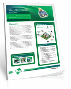
"Digi XBee-PRO 900HP - Best-In-Class Range RF Module"
Long Range Wireless Industrial Mesh
These controllers use Digi XBee-PRO 900HP mesh networking module to move data between devices when direct point-to-point communication is not possible.Each device can automatically relay messages for other devices, allowing data to "hop" across multiple nodes until it reaches the destination. No custom routing is required - devices only need to remain within wireless range of at least one neighboring node.
With typical installations, modules support up to 2 miles of line-of-sight range per hop and up to 8 hops across a mesh network. High-gain antennas can extend point-to-point links significantly under ideal outdoor line-of-sight conditions.
Long Range Wireless
These boards use an embedded XBee-PRO 900HP 900 MHz radio module and communicate through a USB-connected 900 MHz modem on your computer.The modem appears as a standard virtual COM port. You simply send normal ProXR commands to the COM port and the modem forwards them wirelessly to one or more controllers.
This interface supports both point-to-point links and multi-device networks.
💡 Relay Pros Pro Tip:
It worked on my bench... why not through two buildings and a metal wall??
Wireless range is always based on clear line-of-sight between the antennas. While these 900 MHz radios are capable of up to 2-mile line-of-sight range, walls, buildings,
metal structures, and equipment can dramatically reduce usable distance.
The good news is that in many real-world installations you can often find a reliable
"sweet spot" by using antenna extension cables to relocate one or both antennas.
Raising the antenna or moving it to a location where the radios can better "see" each other
will usually make the difference between an unreliable link and a solid connection.
XBee-PRO 900HP RF Module
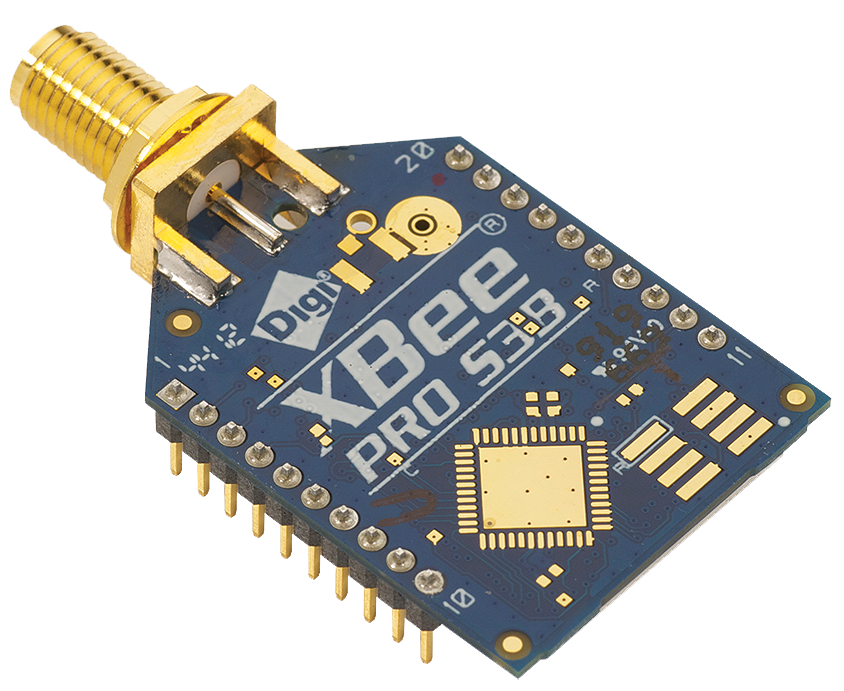 This board is equipped with an XBee-PRO 900HP 900 MHz radio module designed for low-latency,
point-to-multipoint and mesh networking applications.
This board is equipped with an XBee-PRO 900HP 900 MHz radio module designed for low-latency,
point-to-multipoint and mesh networking applications.
The module supports point-to-point, peer-to-peer, and multi-node mesh operation and provides high transmit power for long-range line-of-sight installations.
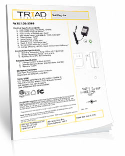
900MHz Wireless Modem (required for PC-to-radio use)
 Not required when integrating into an existing XBee-PRO 900HP mesh network. A 900 MHz USB modem is required to communicate with this controller from a computer
unless the controller is being integrated into an existing 900 MHz XSC mesh network.
Not required when integrating into an existing XBee-PRO 900HP mesh network. A 900 MHz USB modem is required to communicate with this controller from a computer
unless the controller is being integrated into an existing 900 MHz XSC mesh network.
Plug the 900HP-S3B (long-range) modem into the USB port of your computer. The modem appears as a virtual COM port and forwards ProXR commands wirelessly to one or more XSC-compatible controllers.
The modem is available at checkout.
XSC Modem
Communicate with the wireless controller exactly the same way you would communicate with a USB-connected device
💡 Relay Pros Pro Tip:
Getting unreliable wireless performance in high-interference areas?
Large crowds, cell phones, and nearby radio systems can reduce range and reliability. In one installation at a racetrack, we improved signal performance by placing a simple reflector behind the antenna - just a small bowl lined with aluminum foil - aimed toward the transmitting device.
This creates a basic directional "dish" that helps focus the signal toward the receiver. It's a quick, low-cost way to improve reliability when you can maintain line-of-sight between devices.
Regional Compliance
This product contains a Digi XB900HP radio module and is approved for use in the United States, Canada, and other supported regions when configured correctly.Certain regions (including Singapore and others) may require additional certification or licensing depending on your application and deployment.
Canada: Contains IC: 1846A-XB900HP. This device complies with ISED license-exempt RSS standards. Operation is subject to standard conditions.
International customers are responsible for verifying local regulatory and licensing requirements prior to deployment.
900 MHz Relay Videos
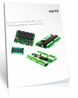
ProXR Expandable Board
This Board includes the XR Expansion Port for adding additional relays to the board. The XR Expansion Boards can be added to control up to 256 relays on this board!
The ProXR Relay Board
ProXR Relay
We've looked at the interface now let's take a look at the board design and programming. The ProXR series controllers are manufactured by hand for a highly accurate and reliable design. Equipped with the XR Expansion Port additional relays can be easily added. Fully tested before they leave the production facility each ProXR controller is ready to stand up to rigorous demands from heat, cold or vibration. The best test of all is the numerous boards in the field from customers all over the world in all sorts of conditions. Take it from us, these controllers will hold up!UXP Expansion
UXP is a standardized data port, specifically for the purpose of speaking to various expansion modules. This controller is equipped with a UXP port, you can take advantage of extended commands to speak to our growing line of I/O expansion modules. You will find the UXP port on models with UXP in the part number.UXP Expansion Modules
UXP Expansion Boards have no on-board brains. They are entirely reliant on the brains of a "master" device. A master device is an NCD controller with a UXP expansion port and a microprocessor of some kind. Most master UXP devices have on-board relays. If you need to add A/D, Contact Closure Inputs or Digital Potentiometers just plug in the appropriate expansion module. You cannot daisy chain different types of modules to the same controller however. In other words if you plug in a potentiometer you will not be able to plug a contact closure or A/D module also. For controllers that are equipped with a UXP Expansion port (and are suitable master devices for UXP Series Expansion) simply look for UXP in the part number. All UXP Expansion Modules have an input and an output so you can simply daisy chain the boards together until you reach the number of contacts you are looking for.- Summary of UXP Modules
- Compatible with UXP Series Controllers ONLY
- Not a stand-alone controller - MUST be used with a UXP Series Controller
- Add Contact Closure Inputs
- up to 256 Inputs - Add Analog to Digital Inputs
- up to 48 Inputs - Add Digital Potentiometer Outputs
- up to 256 Outputs
XR Expansion Port
Most UXP controllers (Master Devices) have an XR expansion port and therefore can accommodate XR Expansion Boards. Typically the XR Expansion port is used to add relays to the main controller (Master Device). Like the UXP Expansion boards the XR Expansion Boards have no on-board brains. They are entirely reliant on the brains of a "master" device. When you run out of relays, just plug in an XR expansion board that is equipped with the kind of relays you need. You can add up to 256 relays including the relays that are on the main controller (Master Device). All XR Expansion modules are compatible with each other so if you want to add different types of relays you can. For controllers that are equipped with an XR Expansion port (and are suitable master devices for XR Series Expansion Controllers) simply look for PROXR in the part number.Using XR and UXP Together
If you select a board that is equipped with both XR and UXP port you can use both ports simultaneously. This allows you to add and control more relays through the XR port plus add A/D, Contact Closures or Potentiometers to the same board through the UXP port. This can all be controlled through the same virtual COM port on your computer. These Expansion Boards can be purchase with the controller or purchased at a later time when you have a need to expand. To use both ports together you will need to select a controller that has UXP and PROXR in the part number to have bothports available on the controller (Master Device).ProXR Enhanced Firmware Installed
This board has ProXR Firmware installed that responds to the full ProXR Command Set. The ProXR Firmware is the industry leading firmware for controlling relays with more commands and functionality than any other board on the market. The list of commands and parameters this board is capable of is extensive. ProXR Enhanced is the newly released enhance version of the ProXR Firmware with more commands, more functionality and better control than ever before! For a detailed list of all the commands with descriptions see our ProXR Enhanced Command Set.Base Station Software
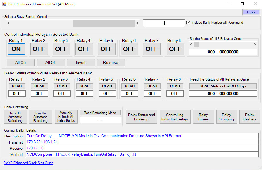 Base Station Software was designed to help you learn the ProXR command set. Explore ProXR features using it's Graphical User Interface. Watch data bytes flow to and from the board, so you easily understand the command execution process. There is no faster or easier way to learn how to automate than Base Station, as it was designed to work with the complete array of communication modules. Base Station software supports every feature of this device - no other controller manufacturer even comes close to offering this type of software.
 SPST Relay Installed
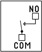 This device has SPST relays installed. SPST Single Pole Single Throw Relays simply connect two wires together.
 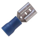 The Common (COM) is the
moving part of the relay that comes in contact with the Normally Open (NO) when the coil to the relay is energized. Wiring is done directly to the Relay terminals using a common 1/4" quick disconnect terminal. To the left is a picture of the connector that will connect to the relay.
The Common (COM) is the
moving part of the relay that comes in contact with the Normally Open (NO) when the coil to the relay is energized. Wiring is done directly to the Relay terminals using a common 1/4" quick disconnect terminal. To the left is a picture of the connector that will connect to the relay.
2-Million Cycles
ProXR series controllers are designed for long life, you should expect to get years of service from your controller and literally 2-million cycles from the relays on board. With a 5-year warranty and a money back guarantee you have nothing to loose! Place your order now, while everything is in front of you.Essential Power Requirements
Applying Good clean power to the board is essential for the operation of the board. Not only for the switching of the relays but the firmware that processes the commands. Without good steady clean power from a regulated power supply the board simply will not function correctly. All boards on the site require 12 VDC power. The PWR12 US power supply is a 120VAC to 12VDC 1.25A 60Hz regulated power supply and it plugs into the barrel connector on the board. The output connector is a 2.1mm I.D. x 5.5mm O.D. x 9.5mm Female R/A barrel connector. We also carry an international power supply with interchangeable adapters for international customers. Learn MoreThis Board is RoHS Compliant
 This board is led free and RoHS Compliant. If your requirements are for RoHS compliant parts this board is manufactured with RoHS compliant led free parts and solder.
16 User-Programmable Timers
The ProXR Series controllers have 16 user-programmable timers. Each independent timer can be assigned to any relay, and can be programmed to hold the relay in the On state, or to pulse the relay at the end of the timer. The ProXR timing features are ideally suited for Watchdog, Keep Alive, and Server Reboot applications, as well as sprinkler systems, gate openers, and lighting applications. Relay Timing Features support two modes of operation: Duration and Pulse. Duration timing is ideally suited where a device should be activated for a period of time. Pulse timing mode is designed specifically for server reboot applications, whereby, if the timer is not reset periodically by your software, the timer will run out and reboot your computer.Easy Software Development
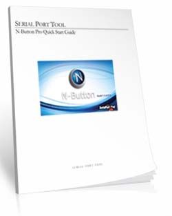
Most of our customers write their own program for controlling these devices. Since you can use almost any programming language, you can use one that is most familiar to you so you don't have to learn a new language. These boards support the Serial Port Profile, meaning they will mount to the computer as a virtual com port. This makes it very easy to send commands to the device.Plug-In for Visual Studio
The NCD Component Library is a plug-in for the Visual Studio 2005/2008 that greatly simplifies the communications to the NCD product line. The samples can be run in Visual Studio and full customization to your needs. Over 40 samples included with this free download! Component Library.5-Year Warranty/Money Back Guarantee
ProXR Lite series controllers are guaranteed against manufacturing and functionality defects for a full 5 years! Not to mention a 30-day money back guarantee! If for any reason you are not happy with a relay purchased from Relay Pros, simply return it within 30 days and we will give you your money back! Controllers that are damaged by our customers will not of course be warranted under any circumstances.Induction Suppression
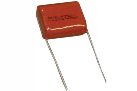 Perhaps the most overlooked aspect of relay control is proper handling of inductive loads. Inductive loads can best be defined as anything with a magnetic coil, such as a motor, solenoid, or a transformer. Controlling a inductive load using this relay board requires an induction suppression capacitor for each relay being used. The purpose of this capacitor is to absorb the high voltages generated by inductive loads, blocking them from the contacts of the relay. Without this capacitor, the lifespan of the relay will be greatly reduced. Induction can be so severe that it interferes with the logic of the board, causing relay banks to shut down unexpectedly. For more information view our Induction Suppression Video.
Shipping
The boards sold are brand new units shipped from our office conveniently located in Missouri. These boards are completely tested before they are released for shipping With so many boards on our site it is impossible to stock boards, please allow two to three days production time for your order to ship. If you have any questions please feel free to call our office at 800-960-4287 or e-mail us at sales@relaypros.com.ProXR Control Is Here!
A more streamlined manufacturing process brings a more durable, reliable and better relay board to the market. Here's a lists of great features:- User Friendly Board Design
- "Wall Wart" or direct power capability
- Relay status light bar
- XR Expansion Port - easily add more relays
- Easy screw terminal connections
- DPDT Relays with 2 connections per relay
- ProXR Features
- Works with the full ProXR Enhanced Command Set
- 8-Channel 8/10-Bit Analog to Digital Converter
- Highly reliable relay with industry leading command set
- 16 programmable timers available
ProXR Videos
Powerful Control, Any Language
The ProXR Command Set gives you precise, reliable control using simple serial commands - compatible with nearly any programming language. Use it directly in your own software or explore every feature using free configuration tools.
The ProXR Command Set
"The industry's most powerful relay command set"
Simple Serial Commands. Serious Control.
The ProXR family of controllers is driven by a powerful, low-level serial command set. You send a short numeric or Hex command to the board - and the board responds immediately.This design keeps your software fast, reliable, and easy to integrate into almost any platform, from small scripts to full automation systems.
How to Send Commands
You can send commands as:
- Decimal byte values
- Hex byte values
What a Command Looks Like
At its simplest, a relay command is only three bytes:254 108 1 - Turn ON relay 1 in bank 1
0xFE 0x6C 0x01 - If you require Hex
254 100 1 - Turn OFF relay 1 in bank 1
0xFE 0x64 0x01 - If you require Hex
The controller processes the command and returns a confirmation byte 85 (0x55 Hex) when the operation completes.
💡 Relay Pros ProTip:
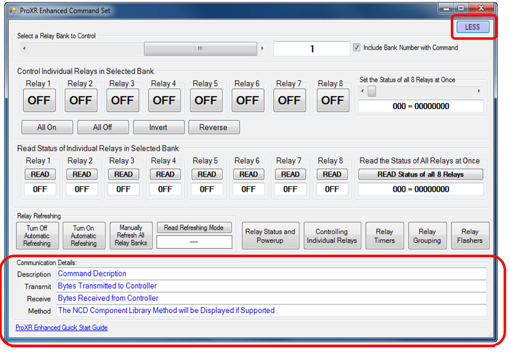
Let Base Station Show You the Command! Base Station software can show you the exact command being sent to the controller. Click the More button in the upper-right corner of the Base Station window to expand the interface and display the command output. When you control relays using the point-and-click interface - turning relays on or off, toggling outputs, or using timing and flasher functions - Base Station displays the actual command being transmitted to the board.
This is extremely useful for programmers. You can perform the function you want in your application and instantly see the decimal or hexadecimal command - the same command you'll use in your programming.
Relay Banks - How Large Systems Stay Simple
ProXR and ProXR Lite controllers organize relays into groups of eight called banks.Each bank contains:
- Relay 1 through Relay 8
Expandable ProXR boards use the same bank structure, but can add additional banks using XR expansion boards as your system grows.
For example:
- An 8-relay controller uses one bank
- A 32-relay controller uses four banks
- A 64-relay setup uses eight banks
- Select a bank
- Send simple relay commands within that bank
Two Ways to Address Relays
You can control relays in two different (and complementary) ways:- Current Bank Commands - select a bank once, then issue fast relay commands
- Bank-Directed Commands - specify the bank directly inside the command
For larger installations, bank-directed commands make software logic easier and more robust.
What You Can Do With the ProXR Command Set
The ProXR command set is designed to support real automation projects - not just basic relay switching.Common operations include:
- Turn individual relays on or off
- Turn multiple relays on or off in a single command
- Read the on/off status of any relay
- Control relays by bank for large systems
- Read analog sensor values (A/D inputs)
- Assign and control internal timers
- Trigger relay pulses and timed operations
- Use onboard logic features such as the Relay Activator system
Designed for Any Programming Language
Because the ProXR command set is pure byte-based serial communication, you can use it from:- Python, C#, C++, Java, Node, LabVIEW, and PLC environments
- Embedded controllers and microcontrollers
- Industrial automation and building control systems
No-Code and Learning Tools
If you do not want to write software immediately, free tools are available:- Base Station Software - explore every command, watch live data, and test automation logic
- N-Button Software - create buttons and automation actions without writing code
Full Command Reference
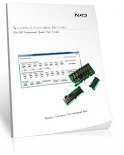
This page is intended as a high-level overview of how the ProXR command system works. For the complete command reference, including all relay, bank, timer, and analog input commands, download the official guide:ProXR Enhanced Quick Start Guide
Relay Grouping - Switch Multiple Relays at the Exact Same Time
Control Neighboring Relays
Relay Grouping lets you control multiple neighboring relays as one logical output.Think of it like building your own multi-pole relay:
- 2 relays → act like a DPDT
- 3 relays → act like a 3PDT
- ...
- up to 8 relays at once in the same bank
How it Works
Relay Grouping adds one extra value to a normal relay command called the Neighbor parameter.The Neighbor value simply means: "Also apply this same command to the next 1-7 relays."
So instead of turning on just one relay...
you turn on that relay plus its neighbors in one shot.
Neighbors must stay inside the same relay bank
For example:- Relay 1 can have up to 7 neighbors
- Relay 8 has no neighbors, because the next relay is in the next bank
💡 Relay Pros ProTip:
Relay Grouping is perfect when you need multiple contacts to move together but still want the flexibility of individual relays also. Instead of hunting for odd multi-pole relay hardware, you can build exactly the behavior you need in firmware.
And if your design changes later? You're not locked into a special relay block.
Prevent Overlapping Relay States
Safe Break-Before-Relay Switching
Some applications require more than simply turning a relay on or off. When controlling motors, actuators, gates, shades, and door systems, it's critical that two opposing relays are never active at the same time.The ProXR firmware includes a built-in Break-Before-Relay command that:
- Turns all relays off
- Waits a short, controlled delay
- Then turns only the selected relay on
Break-Before-Relay Command Example
This example performs a safe switch operation and then activates the selected relay.Decimal: 254 46 0 0
Hex: 0xFE 0x2E 0x00 0x00
When the operation completes, the controller returns: 85 (0x55)
💡 Relay Pros ProTip:
This command is a game-changer for motor control. Use it for gate operators, door controllers, window shades, linear actuators, and any system that uses one relay for "forward" and another for "reverse". By forcing all relays off before energizing the next relay, you protect the motor from being driven in two directions at the same time - a common cause of overheating and motor failure.
This safety behavior is handled entirely inside the ProXR firmware, so your software does not need to manage timing or relay interlocks.
Relay Timers
Relay Timers - Built-In Time Control
ProXR controllers include 16 built-in relay timers that let you turn a relay on for a specific amount of time - without your software having to turn it back off.This is perfect for applications such as:
- Door strikes and mag-locks ("buzz someone in")
- Key-card and access control systems
- Gate and barrier controllers
- Lighting and automation events
Two Simple Timer Modes
ProXR relay timers support two easy-to-use modes:- Duration - turns a relay ON for a specified time, then turns it OFF automatically
- Pulse - waits for the timer to expire, then briefly activates a relay
Simple Duration Timer (Most Common Use)
A duration timer turns a relay ON, holds it ON for the programmed time, and then turns it OFF automatically.You can program:
- Hours
- Minutes
- Seconds
Duration Timer Command Example
Send Bytes (Decimal): 254 50 50 0 0 5 0Send Bytes (Hex): 0xFE 0x32 0x32 0x00 0x00 0x05 0x00
This example activates a relay for 5 seconds, then turns it off automatically.
When the command completes, the controller returns: 85 (0x55)
💡 Relay Pros ProTip:
Relay timers are ideal for door strikes and access control. Instead of having your software turn the relay off, simply send a duration timer for 2-10 seconds. The relay releases the lock, lets the person through, and automatically re-locks the door - even if your software is busy or momentarily disconnected.
Timing is handled inside the ProXR firmware, so your application only needs to send a single command to perform the entire operation.
Note: ProXR controllers do not include a real-time clock. Timers are intended for event-based timing (such as opening a door for a few seconds), not for scheduled calendar-based automation.
Relay Flashers
Relay Flashers - Built-In Blinking and Pulse Control
ProXR controllers include a powerful background relay flasher engine. Once a relay is assigned to a flasher, the firmware automatically turns that relay on and off for you - no software timing loops required.This is ideal for:
- Status indicators and stack lights
- Warning beacons and alarms
- Heartbeat and activity indicators
- Simple pulse or attention signals
Set the Flash Rate (All Flashers)
You can set the flash speed for all active relay flashers with a single command. The speed parameter ranges from 0-255, where:- 0 = fastest flash rate
- 255 = slowest flash rate
Decimal: 254 45 0 128
Hex: 0xFE 0x2D 0x00 0x80
When the command is accepted, the controller returns: 85 (0x55)
💡 Relay Pros ProTip:
Flashers are perfect for visual feedback. For example, use a flashing relay to indicate "system running", "waiting for input", or "fault detected" - while your main software continues doing real work.
Flasher commands can also be combined with relay timers and other ProXR features inside Base Station, making it easy to build pulse, blink, and notification behavior without writing custom timing code.
Base Station Software
Device Command Sets
 Base Station asks the controller which command sets it supports, then displays them when the software launches. Some devices show more command sets, others fewer - it's always based on the board.
ProXR users can access the entire ProXR Command Set to turn relays on/off and run every available function.
Control All ProXR Functions
Turn relays on or off, read relay status, monitor inputs - Base Station gives full ProXR control through a clean point-and-click interface.For programmers, Base Station also shows every command being sent to the board, making it a great tool for learning and development.
Useful Features
There are some useful features to look for when using Base Station Software to control, test, or configure your device:- Links to Quick Start Guides and documentation
- Discovery of network devices with IP address display
- Command Set Window for viewing raw commands (especially helpful for ProXR users)
- Relay Activator with Analog Inputs
Building a Power Budget
Get reliable performance every time! Use these real-world specs to build accurate power budgets, protect your board, and ensure every relay and module runs smoothly under any conditions.
Power & More
"Reliable Power = Reliable Switching"
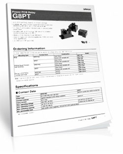
20/30 Amp Board Performance Ratings
This tab brings together the essential performance ratings you'll want to know for NCD 20/30 Amp Relay Controllers and their supported communication modules. You'll find practical electrical requirements, power consumption estimates, operating limits, relay timing details, and more-all based on typical 12VDC operation at 70°F (21°C). Think of it as a reliable snapshot of how our hardware behaves under real-world conditions. Because every installation is unique, some values are estimates and may evolve as designs and testing continue. Use this information as a planning tool to help you choose the right controller, build an accurate power budget, and understand the capabilities built into every NCD 20/30 Amp relay board.20-Amp Relay Amperage Rating
Please Note: The 20-amp Relay is rated for 20 amps on the Normally Open (NO) contact and 10 amps on the Normally Closed (NC) contact.⚠️ Best Practice:
For high-current loads, always use the Normally Open (NO) contact.
The Normally Closed (NC) contact is limited to 10 amps and should only be used for lower-current applications.
Powering from a Battery or Solar Panel?
NCD relay controllers are well-suited for battery-powered and solar-charged applications when operated within the recommended 10 - 15VDC range. This makes them ideal for remote, mobile, and off-grid installations using common 12V battery systems with solar charging. The power consumption data on this page helps you estimate runtime, size your battery, and avoid over-discharge. Staying within the voltage limits ensures stable, reliable operation in long-term battery and solar-powered setups.💡 Relay Pros Pro Tip:
When powering a controller from a battery or solar power, keep voltage between 10-15VDC for reliable operation. Falling outside this range can cause unstable behavior or unexpected resets.
| Specs of NCD SPDT Relay Boards | Minimum | Nominal | Maximum | Notes |
| Operational Voltages | 10VDC | 12VDC | 15VDC | |
| Standby Power Consumption | 35mA | 100mA | 200mA | No Active Relays, No Com Module |
| Relay Power Consumption | 28mA | 35mA | 60mA | Consumption of Each Activated Relay |
| Operational Temperature Range | -40°F (-40°C) | 70°F (21°C) | 185°F (85°C) | Theoretical Component Limits Shown |
| Storage Temperature Range | -67°F (-55°C) | 70°F (21°C) | 185°F (85°C) |
Theoretical Component Limits Shown |
| Operational Ambient Air Humidity | 0% | 50% | 70% | Non-Condensing Humidity Values Shown |
| Relay Activation Time | 15ms | Needs Further Validation | ||
| Relay Deactivation Time | 10mS | Needs Further Validation | ||
| Operational Life Mechanical | 10,000,000 | Component Operation Rating | ||
| Operational Life Electrical | 100,000 | Component Rating at Maximum Load |
Communication Modules
Communication Module Specifications
This table provides a quick, clear overview of all NCD Communication Modules. While each module operates at 3.3VDC, the values shown here reflect the impact on a 12VDC master controller at 70°F (21°C). Use the maximum ratings for power-budget planning - they represent short-term peak consumption and may include estimated values that are updated as modules evolve.| Specs of NCD Communication Modules | Minimum | Nominal | Maximum | Notes |
| Operational Temperature Range | -40°F (-40°C) | 70°F (21°C) | 185°F (85°C) | Theoretical Component Limits Shown |
| Storage Temperature Range | -67°F (-55°C) | 70°F (21°C) | 185°F (85°C) | Theoretical Component Limits Shown |
| Operational Ambient Air Humidity | 0% | 50% | 70% | Non-Condensing Humidity Values Shown |
| USB Module Power Consumption | N/A | N/A | N/A |
USB Modules are Powered by the USB Port Do Not Consume Device Current |
| RS-232 Module Power Consumption | 10mA | 20mA |
|
|
| Ethernet Module Power Consumption | 58mA | 82mA | 100mA | |
| WiFi Bluetooth USB Module Power Consumption | 37mA | 50mA | 100mA | Up to 300 Foot Indoor Wireless Range, Unobstructed. Up to 50 Foot Range Through Walls |
| 900MHz Wireless Module Power Consumption | 13mA | 30mA | 50mA | Up to 1,000 Foot Indoor Wireless Range, up to 2 Mile Outdoor Wireless Range using Included Antennas. Up to 28 Miles Outdoor Wireless Range using High-Gain Antennas. |
| KFX Wireless Key Fob | 11mA | 15mA | 25mA | Up to 200 Feet Outdoor Wireless Range using 1, 2, 3, 4, or 5 Button Key Fobs. Up to 700 Feet Outdoor Wireless Range using 8-Button Remotes |
A/D Inputs
AD8 Analog Input Usage Notice
Analog inputs should never have voltage applied when the controller is powered down. If your application requires voltage to remain on an input, add a 220-ohm current-limiting resistor to each channel to protect the controller from damage. Keep all analog inputs within the 0 - 5VDC range - exceeding this limit can permanently damage the on-board CPU. Most inputs include a 10K pull-up or pull-down resistor to keep the line stable when unused, but note that this resistor may introduce a slight bias in readings for certain sensors.Power Supply Available
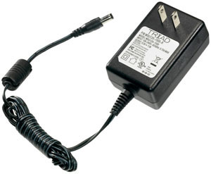 The PWR12 is regulated power supply providing clean power necessary for
the performance of these boards. The PWR12 US power supply is a 120VAC to 12VDC 1.25A 60Hz regulated
power supply and it plugs into the barrel connector on the board. The output connector is a 2.1mm I.D. x 5.5mm
O.D. x 9.5mm R/A barrel connector.
The PWR12 is regulated power supply providing clean power necessary for
the performance of these boards. The PWR12 US power supply is a 120VAC to 12VDC 1.25A 60Hz regulated
power supply and it plugs into the barrel connector on the board. The output connector is a 2.1mm I.D. x 5.5mm
O.D. x 9.5mm R/A barrel connector.
Click Here for More
Induction Suppression
Controlling
an inductive load using our relay controllers requires the use of induction suppression capacitors. The purpose of this capacitor
is to absorb the high voltages generated by inductive loads, blocking them from the contacts of the relay. Without this capacitor,
the lifespan of the relay will be greatly reduced. Induction can be so severe that it electrically interferes with the microprocessor
logic of our controllers, causing relay banks to shut themselves down unexpectedly.
Click Here for More
N-Button Lite
 N-Button
Lite is software that allows you to configure buttons to control relays and read the status of those relays without programming. You
can also create meters for reading variable input sensors connected to the board in real time!
N-Button
Lite is software that allows you to configure buttons to control relays and read the status of those relays without programming. You
can also create meters for reading variable input sensors connected to the board in real time!
Relay Timer R16X
 Relay Timer
Software allows you control each relay independently from a time schedule you create! The software can be installed on a server or PC and uses the
computers time for an accurate relay control. Enter the board's IP address in the software and access it over the network.
Change and override the time schedule from anywhere on the network the software is loaded. Look for Relay Timer R16X during checkout.
Relay Timer
Software allows you control each relay independently from a time schedule you create! The software can be installed on a server or PC and uses the
computers time for an accurate relay control. Enter the board's IP address in the software and access it over the network.
Change and override the time schedule from anywhere on the network the software is loaded. Look for Relay Timer R16X during checkout.
Quick Timer R16X
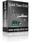 QUICKTIMER_R16X Software
supports turning on/off each relay automatically during the predetermined duration. First set the duration that you want the sequence to be active.
Time periods can then be set where the relay is energized within the set duration. Look for Quick Timer R16X during checkout.
QUICKTIMER_R16X Software
supports turning on/off each relay automatically during the predetermined duration. First set the duration that you want the sequence to be active.
Time periods can then be set where the relay is energized within the set duration. Look for Quick Timer R16X during checkout.
Software Options

 Not a programmer and these boards look intimidating? Don't worry. Powerful software tools make it easy to get connected, discover attached devices, monitor inputs in real time, and control relays without writing a single line of code. Create on-screen buttons, desktop meters, timed events, and automated actions that respond to inputs, schedules, or system conditions - all from an intuitive graphical interface.
Base Station
Base Station software supports every feature on any ProXR board - no other controller manufacturer even comes close to offering this type of software. Download Base Station.
Base Station Software
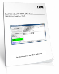
Compatible with ALL Boards on This Site
Base Station is a free software download that works by talking directly to your controller to identify the model, then automatically loads the correct graphical interface for controlling and testing that device. It's a great way to learn how any NCD controller works and doubles as a powerful diagnostic tool to verify your device is operating as designed.Base Station exercises every supported feature on every supported device. For learning, testing, and troubleshooting NCD boards, this is the ultimate reference tool.
User Interface
Base Station gives you a list of command sets supported by your controller. Just click any item once to open the custom graphical interface that was created alongside the firmware. Each command set corresponds with a module installed inside your device."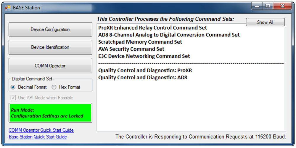
Device Identification
Click the Device Identification window to view important read-only info about your controller.Watch for the field labeled "Documentation Related to this Controller" - it's a complete list of articles connected to your device. Click any entry to open it. (Internet required.)
All devices released in 2012 and later support Device Identification.
Device Command Sets
Base Station asks the controller which command sets it supports, then displays them when the software launches. Some devices show more command sets, others fewer - it's always based on the board.
ProXR users can access the entire ProXR Command Set to turn relays on/off and run every available function.
Control All ProXR Functions
Turn relays on or off, read relay status, monitor inputs - Base Station gives full ProXR control through a clean point-and-click interface.For programmers, Base Station also shows every command being sent to the board, making it a great tool for learning and development.
Useful Features
There are some useful features to look for when using Base Station Software to control, test, or configure your device:- Links to Quick Start Guides and documentation
- Discovery of network devices with IP address display
- Command Set Window for viewing raw commands (especially helpful for ProXR users)
- Relay Activator with Analog Inputs
Configure Buttons
N-Button Lite lets you create on-screen buttons to control relays and view their status - no programming needed. You can also build real-time meters to monitor variable input sensors connected to your board.
N-Button Lite - Full Relay Control
Relay Software
N-Button Lite is third-party software (sold separately) that gives you full relay control and real-time A/D input monitoring without writing a single line of code. It may look simple at first glance, but don't let that fool you - this is a surprisingly powerful tool with a wide range of real-world applications.Create desktop buttons and meters, monitor live input values, and control relays instantly - all from an intuitive point-and-click interface.
Create Buttons & Widgets
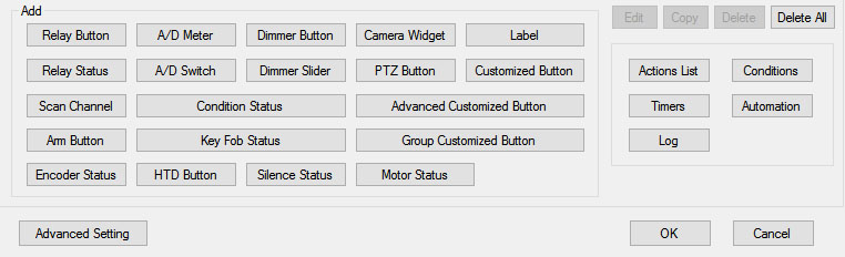 N-Button Lite/Pro lets you build floating desktop widgets that can:
- Control relays and read inputss
- Create buttons to control relays
- Read A/D inputs
- Create live meters from inputs
- Launch applications
N-Button also includes special widgets designed specifically for the boards on this site.
Lite vs. Pro
N-Button Lite includes the same buttons and widgets as the Pro version, but is limited to 16 total widgets. It's ideal for maller projects or cost-conscious applications where you still want full functionality. If your project grows, N-Button Pro removes the limit and supports up to 255 widgets.USB and Network Compatible
N-Button Lite works over Serial/USB or Network connections between your computer and the relay board. Add or modify widgets easily using N-Button Lite Manager to create the exact look and behavior you want. N-Button Lite supports this relay board and any ProXR Relay board with up to 16-widgets.Control Multiple Boards
N-Button Lite software can control multiple devices connected to the same computer or network, allowing you to manage relays, inputs, meters, and automation across several boards from a single interface. Use the built-in Device Manager to easily add, remove, or modify boards and maintain a clear list of all connected devices. Each device is handled independently, making it easy to build scalable systems without adding complexity.For example, a single PC can monitor A/D inputs on one board while controlling relays on multiple network-connected boards.
Time Control Software
 We offer two timer software options to support different types of automation needs: Relay Timer and Quick Timer. Relay Timer is designed for time-of-day scheduling, allowing relays to turn on and off automatically based on the computer's clock - ideal for daily routines and long-term automation. Quick Timer focuses on duration-based control, running relay sequences for a defined length of time that you manually start, making it well suited for test cycles, timed processes, and repeatable sequences.
 Choose the timer that best matches whether your application depends on when an action occurs or how long it runs.
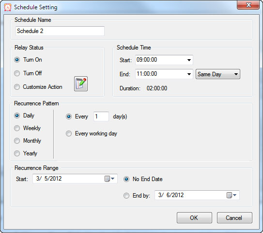
Time Schedule Relay Control
Relay Timer software makes it easy to turn relays on and off automatically at times you choose. Create repeating schedules - daily, weekly, monthly, or on specific days - and connect using USB, serial, or your network.
Relay Timer
Time Schedule Control
Relay Timer is third-party software (sold separately) that works with all ProXR and ProXR Lite relay controllers and supports every available interface - USB, wired, wireless, and network. No matter how your board is connected, Relay Timer communicates seamlessly to deliver reliable, scheduled relay control.Precision Scheduling Using Your Computer's Clock
 Relay Timer uses the computer's system clock to maintain accurate, drift-free timing. This ensures relay actions stay perfectly synchronized with other applications running on the same machine, such as time clocks or automation software.
A high-resolution timing engine - similar to those used in multimedia applications - provides timing accuracy down to 5 - 10 milliseconds, making Relay Timer well suited for real-time and precision-based control tasks.
High-Speed, Multi-Relay Control
Relay Timer can update up to eight relays simultaneously using the ProXR and ProXR Lite communication protocol. When speed matters, all eight relays can be updated in approximately 30 milliseconds.In multi-relay applications, Relay Timer calculates the state of all relays together, even though each relay operates independently. This ensures fast, coordinated, and predictable behavior across complex schedules.
Take Manual Control
At any time, you can manually take control of a relay to interrupt the active schedule. Resume automatic operation instantly or set a specific time for the software to return to scheduled control - ideal for maintenance, testing, or temporary overrides such as school bells for assemblies.Duration-Based Relay Control
QuickTimer lets you turn relays on or off for a set amount of time - just like setting a timer on an oven or microwave. Once the timer starts, the software handles everything automatically.
Quick Timer
Compatible with ProXR & ProXR Lite Boards
Quick Timer is third-party software (sold separately) that works with all ProXR and ProXR Lite relay controllers and supports every available interface, including USB, wired, wireless, and network connections. The software automatically communicates with your board regardless of how it's connected, making setup quick and straightforward. Designed for responsive, duration-based control, Quick Timer delivers fast, reliable relay operation for timed sequences, test cycles, and repeatable automation tasks.Duration-Based Relay Control (Not Time-of-Day Scheduling)
Quick Timer is designed for applications where how long a relay is energized matters more than what time of day it activates. Instead of using the computer's clock, Quick Timer runs sequences based on a defined time duration.
A sequence is manually started and can:
- Run once and stop automatically, or
- Loop continuously until manually stopped
Flexible Time Sequences Within a Single Duration
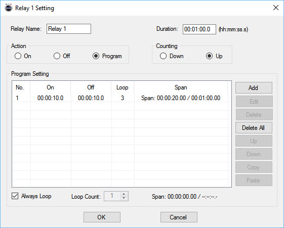 Quick Timer allows you to define a total run duration first. Within that duration, each relay can follow its own independent on/off timing pattern.
Example: 30-Second Sequence
- Relay 1 turns on for 5 seconds, then off for 5 seconds
- Relay 2 turns off for 5 seconds, then on for 5 seconds
- Relay 3 turns on for the first 10 seconds, then off for 20 seconds
- Relay 4 remains off for 10 seconds, then turns on for 20 seconds
Independent Control Per Relay
Each relay can be configured with its own timing behavior while remaining synchronized within the overall sequence duration. This allows complex, coordinated relay patterns without requiring scripting or programming.Manual Override at Any Time
Manual control is always available. Interrupt the active sequence to toggle any relay as needed, then return to automatic operation immediately or at a user-defined time.Built for Real-World Reliability
Quick Timer is designed to handle real-world operating conditions, including communication interruptions, power loss, and system instability. Rather than assuming perfect conditions, the software focuses on predictable behavior and clear user control when issues occur.Confirm Relay Timing in Seconds
Why wait hours - or days - to see if your automation works? Time Travel lets you fast-forward your computer's clock to instantly test Relay Timer schedules and Quick Timer sequences. Jump ahead in time, watch relays trigger exactly when they should, fix issues fast, and get your setup right the first time - no DeLorean required.
Time Travel
Fast-Forward Time for Testing & Automation
Time Travel software answers the age-old question of time travel - at least for your PC. This free utility lets you override and accelerate your computer's clock, making it easy to test time-based automation without waiting in real time. Time Travel is included with Relay Timer, Quick Timer, and N-Button software and is also available as a free standalone download.Instead of waiting hours or days to verify schedules, you can fast-forward time and confirm relay behavior in seconds - saving time, frustration, and repeated test cycles.
Make Time Run Faster
Time Travel can temporarily override your computer's system clock and adjust how fast time runs. Increase the clock speed to simulate long periods instantly - for example, at 3600x speed, a full day passes in just 24 seconds.This makes it easy to validate schedules, sequences, and automation logic without waiting for real-world time to pass.
Ideal for Bench Testing & Development
Time Travel is especially useful for testing any software that relies on the computer's clock, including:
- Relay Timer
- Quick Timer
- N-Button
- Other scheduling or automation applications
Presets & Automatic Time Recovery
Time Travel includes preset configurations that allow you to load saved time and speed settings quickly. Users can create, save, and export presets for future use, and the software remembers the last configuration when restarted.To protect your system, Time Travel automatically restores the computer's clock to the correct local time when the program exits. The system time is only affected while the software is running.
Simple to Use
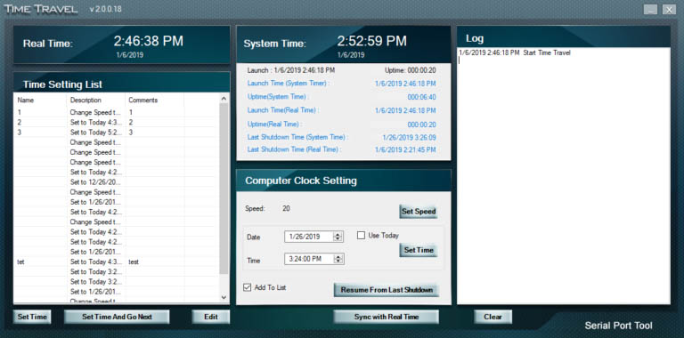 Using ime Travel is straightforward:
- Download and unzip the software
- Run TimeTravel.exe as Administrator
- Current Running Speed - Adjusts how fast the computer clock runs
- Set Time - Changes the computer clock to a specific date and time
- Resume From Last Shutdown Time - Restarts from the last simulated computer time if the system shut down unexpectedly
- Sync with Real Time - Returns the clock to real-time operation (when speed is set to 1x)
Component Library
Visual Studio Samples
 The NCD Component Library is a plug-in for the Visual Studio 2005/2008 that greatly simplifies the communications to the NCD product line. The samples can be run in Visual Studio and fully customizable to your needs. Over 40 fully functional fully working samples are included in this free download.
 Visit our Component Library Page to view all the samples available.